Page 14
6 - After it has been determined that each appliance re
maining connected to the common venting system
properly vents when tested as outlined above, return
doors, windows, exhaust fans, fireplace dampers and any
other fuel burning appliance to their previous condition of
use.
7 - If improper venting is observed during any of the
above tests, the common venting system must be
corrected.
Horizontal Venting
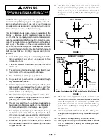
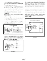
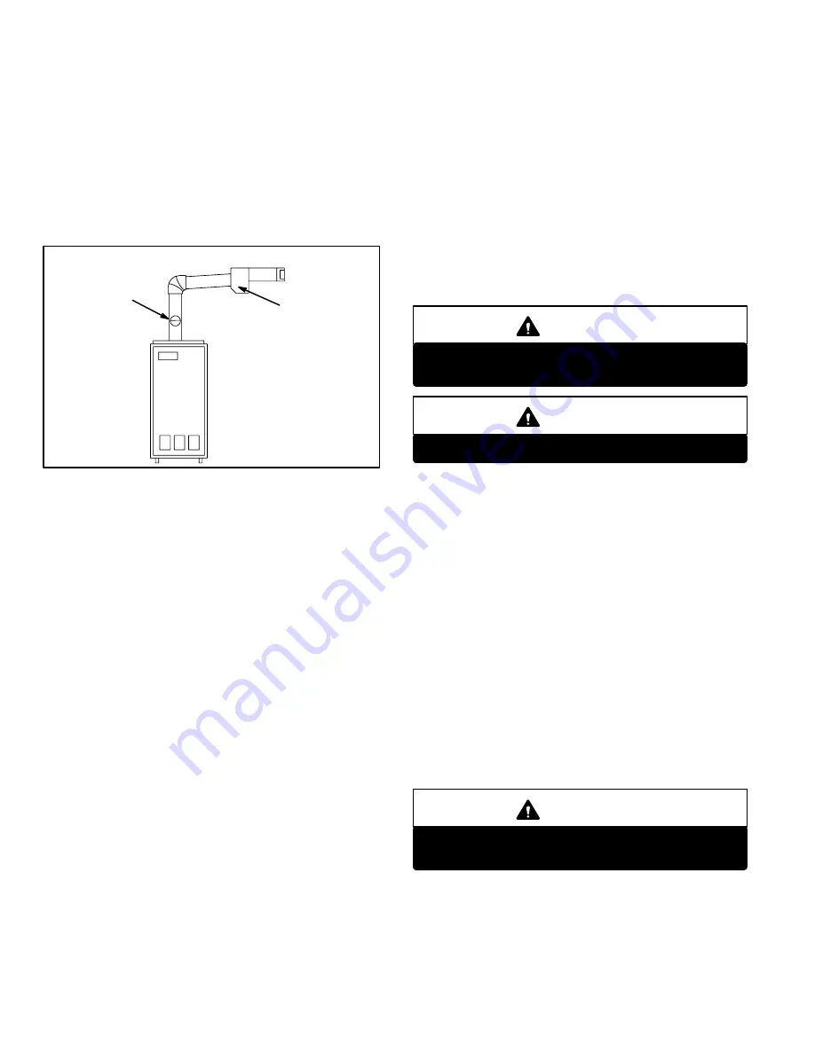
HORIZONTAL VENTING
BAROMETRIC
CONTROL*
CONTROL FOR
HORIZONTAL
VENTING
FIGURE 15
*When using indoor air,
barometric control must be
installed in the horizontal
venting system and located
within 18" (457 mm) of vent
outlet of furnace.
When using direct connection,
barometric control must be
installed in the intake air pipe.
The O24 is approved for horizontal venting with the fol
lowing mechanical vent systems:
Tjernlund (sideshot) #SS1C and Field Controls #SWG-5 with
the CK-61 control kit. Refer to manufacturers' installation
instructions for proper installation procedures and service parts
information.
Do not common vent with any other appliance when using
sidewall vent system.
Maximum permissible vent length is 70 equivalent feet (21.3
m). Minimum length is 15 equivalent feet (4.6 m). Each 90
el
bow is equal to 6 feet (1.8 m) of straight pipe, each 45
elbow is
equal to 3 feet (0.9 m) of straight pipe. Minimum vent pipe di
ameter is 4" (102 mm) for the O24/OF24-70,-105/120 (R) and
5" (152 mm) for O24/OF24 (R)-140/154, however vent pipe of
5" (127 mm) and 6" (152 mm) is permissible. Calculate the
equivalent vent pipe footage from the furnace to the mechani
cal vent system (Tjernlund or Field Controls) by adding the
straight vent pipe length and the equivalent elbow lengths
together.
The barometric draft control must be used in horizontal (side
wall) venting system. It must be located within 18" (457 mm) of
the furnace vent outlet. See figure 15 for barometric draft con
trol location.
III-STARTUP
A-Preliminary and Seasonal Checks
1 - Inspect electrical wiring, both field and factory installed for
loose connections. Tighten as required.
2 - Check line voltage. Voltage must be within range
listed on the nameplate. If not, consult the power
company and have voltage condition corrected be
fore starting unit.
B-Bleeding Fuel Line
Before starting unit, make sure the oil tank is adequately
filled with clean No. 1 or No. 2 furnace oil.
NOTE - Water, rust or other contaminants in oil supply sys
tem will cause malfunction and failure of the internal parts of
the fuel unit.
CAUTION
Never burn garbage or paper in the heating sys
tem. Never leave papers near or around the unit.
CAUTION
Blower access door must be in place before start-up.
1 - Set thermostat for heating demand and turn on electri
cal supply to unit.
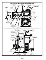
2 - Check initial air adjustment. All units are equipped with
an air adjustment dial on the right side of the burner.
See burner parts arrangement illustration.
3 - Turn unit on. Place a can or container under the bleed
port located on the fuel pump. Loosen nut on bleed port
to release air and oil mixture from fuel line. Allow mix
ture to escape until a steady stream of oil is emitted
from the port. Drain at least 1/2 pint of oil from the pump.
Retighten nut on bleed port. If unit locks out during
bleed procedure, push reset button on primary safety
control.
NOTE - A two
line fuel system will normally bleed itself
by forcing air back to the tank through the return line.
This type of bleeding procedure is not necessary.
4 - If burner fails to start, push reset button on primary
safety control. See part arrangement illustration.
CAUTION
Do not push the reset button on the primary con
trol more than one time.
5 - If burner fails to light again, refer to the troubleshooting
section in this manual.
6 - Proceed to section IV to complete start up.


