background image

icomfort


Wi-Fi

 7−Day Programmable Communicating Thermostat

Page 55

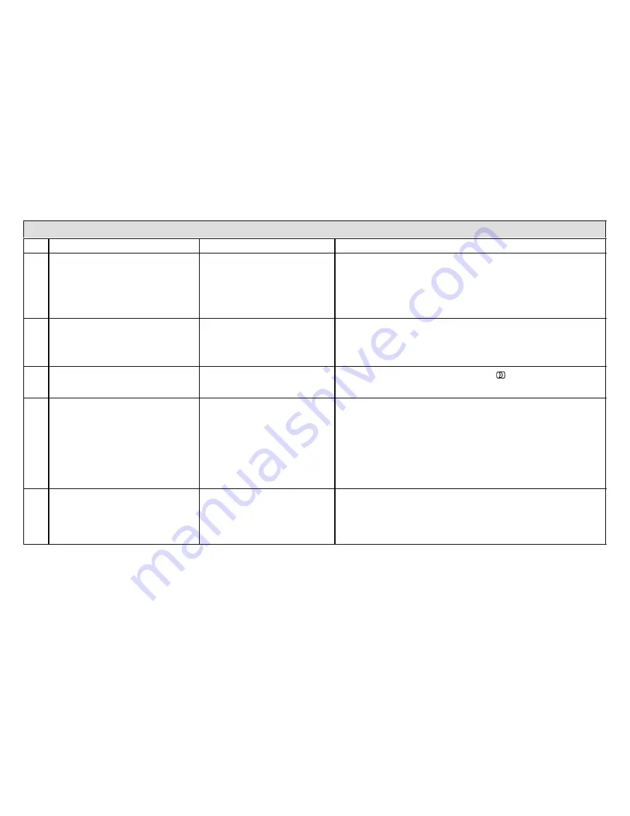
Table 6. Troubleshooting Tips

Bold

 text indicates a button, or text display on the thermostat.

No.

Issue / Problem

Possible Cause

Corrective Action / Comments

1

− No electric heat operation.
− The thermostat 

system setting

does not offer a 

emerg. heat

 choice

on an HP system.

− The thermostat does not offer any

heat

"

 choice on an AC system with

air handler with electric heat.

Electric heat was not manually
configured configured at the Air
Handler Control (AHC) before the
icomfort


Wi-Fi


system discov-

ery

 process at initial power−up.

− Manually configure to discover the electric heat section(s) on the air

handling (see Page 64 or CBX32MV or CBX40UHV manual for de-
tails).

− Re−setup the icomfort system by selecting the 

setup

 button in the

Installer program and press 

start

 to begin 

system discovery

; then

reconfigure the system.

2

Thermostat Displays 

System Wait-

ing

 message and the furnace does

respond to a heating demand (no red

critical alert

 icon or alert messages

are displayed on the thermostat).

The furnace is in watchguard"
mode (moderate alert) and will
not display the red 

critical alert

icon nor be displayed in the
homeowner 

alert


button.

− Go to the installer program 

alert

 button to view all alerts and details

about those alerts.

− If the furnace is in watchguard" mode, the furnace can be reset from

the Home screen by setting the thermostat 

system settings

 to 

off

for 20 sec, then back to 

heat

. Then initiate a new heat demand.

3

Outdoor temperature is not displayed
on the thermostat.

Outdoor Temp Display

 must be

enabled to display the outdoor
temperature on the home screen.

On the home screen, press the right arrow 
then press the 

display settings

 button. Click on 

outdoor temp dis-

play 

button to toggle ON.

4

A humidifier was added to the system
as non−communicating equipment
and the thermostat does not provide
the ability to adjust the RH setpoint.

Humidification Control Mode

 is

set for Display only" which will
not allow the icomfort system to
control the humidifier.

− In the installer program, select the 

equipment

 button. Select Sys-

tem" from the device list using the up/down arrows and press the 

edit

button. Use up/down arrows to select 

Humidification Control Mode

from the list. Select the desired humidifier control mode: 

Basic

Preci-

sion

, or 

Dew Point

. (Basic is the most popular) and press the 

save

button. Follow the red instructions then exit the system.

− If 

Humidification Control Mode

 is not offered as a menu item

choice, the Humidifier must be added to the icomfort system using
the 

Add or Remove Non−communicating equipment

 screen under

the thermostat installer program in the 

setup

 button.

5

The non−communicating outdoor unit
is part of the system, but the thermo-
stat does not display the outdoor unit.

The outdoor unit was not added
as a non−communicating unit dur-
ing initial system setup.

In the thermostat installer program select the 

setup

 button and follow

the on screen instructions until you reach the 

Add or Remove Non−

communicating equipment

 screen; press 

yes

. Select 

Outdoor Unit

Type


from the menu and press the 

edit

 button. Select 

1 Stage AC Unit

or 

2 Stage AC Unit

 and press 

save

. Follow the red instructions then

exit the system.

table continued on next page

Summary of Contents for CBX32MV?06 or later

Page 1: ...s thermostat only as described in this manual INSTALLER S SYSTEM SETUP GUIDE icomfort Wi Fi Thermostat Touch Screen Programmable Communicating Thermostat CONTROLS 506920 01 09 12 Supersedes 05 12 icomfort Enabled Units G71MPP 03 or later XC17 02 or later SLP98 01 or later XP17 02 or later SL280 03 or later XP19 06 or later EL296V 01 or later XC21 05 or later CBX40UHV 02 or later XP21 01 or later C...

Page 2: ...Pump Dual Fuel and Balance Points 32 Gas Heat Control Mode 34 Table 2 Variable Capacity Furnace Operation 35 Table 3 Adjustable Parameters Installer 37 Table 4 Adjustable Parameters User 43 Table 5 Alert Codes and Troubleshooting 45 Homeowner Service Codes 54 Table 6 Troubleshooting Tips 55 Wiring Diagrams 59 Thermostat wire termination in communicating system 63 Table 7 Replacement Controls 72 Se...

Page 3: ...ELLOW Figure 1 icomfort by Lennox system BEST PRACTICES Keep all communication wiring as far away from house electrical wiring and large electrical appliances as possible 15 5m recom mended The thermostat also supports three languages English French Spanish supports air conditioning units or heat pump units with up to four stages of heat two stages of compressor operation 2 stages of heat pump hea...

Page 4: ...ence below After all wiring connections are made apply power to the system 24VAC will power up the thermostat After power is applied to the thermostat for the first time the processor checks the system for installed communicating devices the So Sim ple So Smart So Comfortable screen dis plays followed by Use this thermostat screen Touch press here to continue During the setup process alerts may po...

Page 5: ... 3 Also see Set time and date on Page 7 After changes have been made use save to store the changed data or cancel to exit the screen and return to the list of settings Dealer Number Use the arrows to scroll to the Dealer Number setting Press edit and use the typewriter tool shown in figure 3 to enter your dealer number Press save to store the identification system settings To adjust a setting high...

Page 6: ... per hour 25 15 minutes fan run time per hour 35 21 minutes fan run time per hour 45 27 minutes fan run time per hour Table 1 shows the range condition and defaults for the system settings and indicates the tools used to make changes Table 1 System setting defaults and range system setting range condition default use Time and Date see Page 7 Daylight Saving Time Enabled Disabled Enabled Circulate ...

Page 7: ...Dealer Website Figure 5 View edit time and date When Time and Date screen figure 6 appears enter the correct date as follows Use the left and right arrows to change the month and year Touch a day of the month to select it Press on the hour or minute up down arrows appear to allow change Touch the am pm field to toggle it between am and pm When the correct date and time is set press save to save se...

Page 8: ...ature list Furnace device description Equipment Type Name Furnace back Language Support Equipment Type Name Unit Model Number Unit Serial Number Unit Nominal Capacity Number of Heating Stages Heating Capacity by Stage Indoor Blower CFM Range Control Software Revision Control Model Number returns to system devices screen about back next 9 39 am Aug 15 2012 press about for more information on a high...

Page 9: ... call for heat if there is a humidification demand Sensed outdoor temperature required for some features is provided from one of the following sources A downloaded via Wi Fi when available primary source B sensor furnished with icomfort enabled outdoor units C separate outdoor sensor connected to the furnace or air handler outdoor sensor connections NOTE If no source for outdoor temperature is pre...

Page 10: ... in the device list e g select Outdoor Unit Capacity text turns white Press edit 4b 5 Use arrows 5a to make changes press save 5b Change other red settings if present using a similar process NOTE If the defaults are correct you do not have to make any changes but you must press save 5b When all red text is gone the back button will appear press it to return to the Add or Remove Non communicating e...

Page 11: ...age 15 6 If you want other than the default Basic mode of operation Configure the humidifier as described on Page 15 next back Before adding a humidifier be sure that the humidifier is wired to the furnace or air handler control as shown on the Optional Accessories wiring diagram see Page 61 the entire system is wired powered up and the thermostat has detected the system s installed communicating ...

Page 12: ...ghlight Dehumidifier and press edit 2b Note the current value e g Not Installed 3 Touch one of the radio buttons 3a to select the type of dehumidifier or select Not Installed if removing dehumidifier press save 3b 4 When you scroll to the Dehumidifier device 4a Note the current value e g Humiditrol Click back 4b to return to the Add or Remove screen 1 5 The Add or Remove screen reappears with your...

Page 13: ...changing heating airflow more examples are shown on the next page Use back to return to the previous screen or next to go on A complete list of parameters their defaults and setting ranges begins on page 37 Low Heating Airflow Range is 325 to 450 Default is 400 inc 25 set to 325 cancel save system devices Furnace edit about next resetAll back To adjust a setting highlight it then press Edit System...

Page 14: ...e Point Control Disabled Staged Delay Timers 2nd Stage Delay 3rd Stage Delay Balance Point Control Humiditrol Comfort Adjust Humidification Control Mode Min Dehumidification Setpoint OK Humid Boundary Disabled Enabled Select one Balance Point Control cancel save Figure 12 Accessing device to modify Staged Delay Timers 2nd Stage Delay 3rd Stage Delay Lock In 2nd stage HP by Outdoor Temp Balance Poi...

Page 15: ...ve 5b Repeat for other red settings You will not be able to advance to the next step until all red settings have been removed 6 Press the back button to return to Adjust a setting screen NOTE If the defaults for the settings shown in red you are not required to make any changes but you must go into the edit tool and press save 5b When all red text is gone the backbutton will appear press it to ret...

Page 16: ...ess save 5b After saving check that the current value now shows the new selection 6 Press the back button to return to Adjust a setting screen 1a 1b 2a system devices System Air Conditioner Furnace Thermostat Humiditrol Maximum Overcooling Midpoint Overcooling Minimum Overcooling Select one Humiditrol Comfort Adjust cancel save 3b 3a System 3rd Stage Delay 4th Stage Delay Lock In 2nd Stage HP by O...

Page 17: ...se arrows 4a to highlight any red colored text in the list e g select Min Dehumidification Setpoint Press edit 4b 5 Use arrows 5a to make changes press save 5b Change other red settings e g Auto Changeover Humidif Deadband using a similar process 6 Press the back button to return to Adjust a setting screen NOTE If the defaults are correct you do not have to make any changes but you must press save...

Page 18: ...ons are true except cooling demand may or may not be present Also note that Maximum overcool from cooling setpoint is 2ºF Deadband temperature is limited to a minimum of 5ºF instead of 3ºF in BASIC or DISPLAY ONLY mode because of 2ºF overcooling Humiditrol or Auxiliary Dehumidifier mode requires NOTE Systems using icomfortt and a dehumidifier Dehum jumper on furnace air handler control does not ne...

Page 19: ... all of the tests press select all All boxes in the list of tests will be checked Or touch box es next to test s to run certain tests After the tests have been started the screen will describe which test is run ning and shows a diagnostic summary of each test see figure 19 After re viewing the results and concluding that no further tests are needed press next to proceed to next test The technician...

Page 20: ...up equipment parameters and edit details of de vices in the system without having to re run the setup program When the press start screen figure 21A appears press start The Equipment pa rameters screen figure 21B will open You may view information about or modify communicating devices as described earlier in the setup pages be ginning on page 14 Use the arrows to select a device and press edit Use...

Page 21: ...on if you have completed the required setup or use diagnostics but ton to analyze the system see Page 21 or use equipmentbutton again if you want to make any further changes to device details Table 3 on on Page 37 shows a list of Editable Parameters for the currently available devices designed to communicate in this system Other devices and additional parameters may be added at a later time Check ...

Page 22: ... selected use view active to list all active alerts for selected devices If there are no alerts the display will show There are no new alerts that require service If there are alerts these are stored for recall but only one alert will appear in the box at a time see figure 24B Use the next button to advance through all the alerts If only one alert is present the next button will not appear Alerts ...

Page 23: ...s No Alerts Figure 25 Press back to return to the system and device alert screen figure 24A Page 23 equipment tests setup 9 39 am Aug 15 2012 back No Alerts Figure 25 Cleared alert confirmation View cleared alerts A history of cleared alerts allows the installer to review cleared alerts This information can help diagnose problems Use the arrows to select either se lect all or check an item from th...

Page 24: ...r left corner of the HOME screen see START HERE The screen changes from the Home Screen to the WI FI SET TINGS screen 2 Press the Wi Fi enable button 3 Press next as necessary then press accept after reading the User Agreement 4 Press NETWORK SETTINGS this screen shows a graphical view of buttons representing Wi Fi options OPEN and SECURE wireless networks and a button for creating a new access po...

Page 25: ...the registration button on the thermostat and re ceiving the consumer portal register link from your email on your computer is from 5 to 15 minutes After registration has been completed any available firmware downloads will immediately start downloading to the thermostat REGISTRATION register enter your email re enter your email Register with iComfort thermostat to enable remote access and online ...

Page 26: ... total control of your Lennox icomfort system Registering your thermostat will allow you to remotely access it from anywhere in the world on any device with an internet connection Please com plete your Lennox icomfort registration by clicking the link be low Register NOTE if the customer has already setup an account click the Click Here button to access that account Click on the Register link the ...

Page 27: ...able Apps and customizable skins using the links on the right side of the page From the welcome page you may also click on links to launch an interactive demo or learn more abouticomfort Wi Fi How Do I Turn on Skins on the icomfort Wi Fi Thermostat From the thermostat Home screen press then display setting then power save buttons From the pop up menu select skins The skin picture will appear after...

Page 28: ...Figure 32 Enter installation setup mode from home screen A message screen stating Qualified Lennox equipment installer warning screen appears Figure 33 Press yes to proceed no returns to the home screen WARNING The following screens are intended for use by qualified Lennox equipment installers only Do you want to proceed yes no Figure 33 Qualified Lennox equipment installer warning When you press ...

Page 29: ...the program goes through the same setup as the initial setup process which begins on Page 4 NOTE Compatible device found screen shown below appears only when a device has been removed and replaced with a compatible device Missing Device Equipment Type No Model No control model no Serial No control serial no Found Compatible Device Equipment Type No Model No control model no Serial No control seria...

Page 30: ...is default 20 minutes in cases when the previous stage of heating or cooling will not raise or lower the room tempera ture to the setpoint in a given time When Disabled is selected all stage delay timers are disabled This means stages are changed based on the temperature and not their timer delays NOTE The 2nd Stage Delay Timer when Staged Delay Timers is Enabled is used for both HEATING and COOLI...

Page 31: ...etpoint will equal the current program schedule setpoint 5 When a new program schedule period starts then the New SSR set point will equal the new program schedule period s setpoint unless there are two or more program periods within the 2 hour window In this case SSR will track the highest heat setpoint or the lowest cool set point found in the 2 hour window 6 SSR will NOT run during a program sc...

Page 32: ...compressor operation is not allowed Since the heat pump is not as effective at a lower outdoor temperatures it may be more comfortable to use the auxiliary electric heat or the furnace in dual fuel sys tems it may be more economical to satisfy a demand for heat The low bal ance point options are from 20 F to the high balance point temperature The setpoint can be adjusted in 1 0 F steps High Balanc...

Page 33: ... lockout T stat heat demand T stat heat demand YES YES NO between HBP and LBP at or above HBP COMPRESSOR ONLY EITHER COMPRESSOR OR FURN HEAT FURN ONLY 50ºF OUTDOOR TEMPERATURE defaults shown HBP FURNACE LOCKOUT TEMPERATURE NOTE 1 Each Heat Pump and Furnace Heat stage will oper ate until it meets the demand or until its stage timer lapses 20 minutes by default If the timer lapses before the demand ...

Page 34: ...nutes up to 100 firing rate T stat demand sat isfied in less than 5 minutes T stat demand sat isfied in less than 5 minutes Increase firing rate to calculated 2nd stage firing rate Increase firing rate to calculated 3rd stage firing rate Increase firing rate to 100 until thermostat demand is satisfied THERMOSTAT DEMAND SYSTEM IDLE YES NO Differential less than 3rd stage differential YES NO Differe...

Page 35: ... temperature previous heat cycle times and target setpoint to determine the starting firing rate and any required firing rate increases or decreases during the thermostat demand During a heat demand the icomfort thermostat monitors the differential be tween setpoint and room temp As this differential increases and reaches field adjustable levels stages the thermostat will increase firing rate ac c...

Page 36: ...trackingVariable Capacity the thermostat uses a Proportional Integral Algorithm PIA to control firing rates of the furnace The algorithm in the Load tracking Variable Capacity provides much more precise control over the furnace than the Variable Capacity algorithm Interesting points about the Proportional Integral Algorithm PIA The further temperature is from the current set point the higher PIA s...

Page 37: ...at Control Mode SLP98 G71MPP Load Tracking Load Tracking Variable Capacity Variable Capacity Staged SL280 EL296 Staged Staged only Max Heat Setpoint 90ºF 40 to 90ºF 1ºF Min Cool Setpoint 60ºF 60 to 99ºF 1ºF Heat Cool Stages Locked In Disabled Enabled Disabled 1st Stage Differential 1 0ºF 0 5 to 3ºF 0 5ºF 2nd Stage Differential 1 0ºF 0 5 to 8ºF 0 5ºF 3rd Stage Differential 0 5ºF 0 5 to 8ºF 0 5ºF 4t...

Page 38: ...fier is installed Humidification Control Mode Display Only Display Only Basic Precision Basic Dew Point Con trol Precision Dew Point Control Autochangeover Humidification Deadband 5 5 to 10 1 Max Humidification Setpoint 45 15 to 45 1 Min Dehumidification Setpoint 40 40 to 60 1 Max Dehumidification Setpoint 40 40 to 60 1 OK Humid Boundary 50 45 to 60 1 Outdoor Temperature Reading Calibration 0 10ºF...

Page 39: ... delay 3 ON 82 7 5min OFF No delays 4 ON 50 30s 82 7 5min OFF 50 30s Low Heating Airflow nnnn CFM See Note 3 at end of table NOTE CFM Default and Values Settings are depen dent on the tonnage of the unit 5CFM High Heating Airflow 5CFM Continuous Indoor Blower Airflow 10CFM Humidification Airflow 10CFM Dehumidification Airflow 70 60 to 80 percentage of reduction of High Cooling Airflow 1 Delays Hea...

Page 40: ...eat Pump present Not used on Non Comm IFC Gas Heat Airflow Settings Heating Airflow Control Type variable capacity furnaces only 0 Fixed CFM 0 1 1 DATS installed 0 Fixed CFM 1 Fixed DAT Low Heating Airflow CFM min heat DIP SW See furnace docu mentation IOM or engineering hand book for size spe cific information 25 Heating Airflow Control Type 0 See furnace documen tation IOM or engineer ing handbo...

Page 41: ...ble Min CFM Max CFM 25 2 stage Outdoor Unit present 1 2 HP blower Min CFM Max CFM 25 1 HP blower Airflow Profile Cooling DIP SW 0 3 1 Outdoor Unit present 0 A ON 50 30s 82 7 5min OFF 50 30s 1 B ON 82 7 5min OFF No delays 2 C ON No delays OFF 45sec delay 3 D No delays Heat Pump Airflow Settings High Heat Pump Airflow CFM 100 OU tons 400CFM Min CFM Max CFM 25 Heat Pump present 1 2 HP blower Min CFM ...

Page 42: ...ntroller algorithm support Percent of High Cooling Airflow Note 1 Minimum Outdoor Unit Cooling Stage as a percentage of High Cooling Airflow value is rounded up to the closest number on 25 CFM resolution Note 2 Minimum Outdoor Unit Heating Stage as a percentage of High Heat Pump Airflow value is rounded up to the closest number on 25 CFM resolution Note 3 All communicating Installer Parameters def...

Page 43: ... Dealer Website www lennox com keyboard input screen Language Displayed English English French Spanish Temperature Display Scale F F Fahrenheit C Celsius Clock Format 12H 12 Hour 24 Hour Screen Lock out Unlocked Unlocked Partially Locked Fully Locked Backlight Setting Always On Power Save Always On Backlight Intensity 100 20 to 100 20 Outdoor Temp Display is OFF is OFF is ON Indoor Humidity Displa...

Page 44: ...Months 6 Months 12 Months 24 Months Custom Time UV Bulb Timer Disabled Disabled 3 Months 6 Months 12 Months 24 Months Custom Time Maintenance Timer Disabled Disabled 3 Months 6 Months 12 Months 24 Months Custom Time PureAir Timer Disabled Disabled 3 Months 6 Months 12 Months 24 Months Custom Time THERMOST AT Go to equipment button and scroll to Thermostat NOTE These settings apply to the thermosta...

Page 45: ...med to work The system will only use the heat pump to warm your home Notification only Outdoor Temp is above the High Balance Point Indoor Unit furnace or air handler will not be used to service a heating demand 29 Critical Stat The thermostat is reading an indoor tem perature that is higher than 99ºF The thermo stat will not allow any heating operation to begin until it senses a temperature lower...

Page 46: ...he system in diagnostic mode and verify that it matches actual equipment operation Check for other alarms codes that may be preventing the system from operating as expected Step 1 Check all heating equipment to determine cause Step 2 Recycle power System will clear code when it detects condition has cleared 39 Critical Stat The system has not been able to turn on the cooling for more than 45 minut...

Page 47: ...n the outdoor unit responding to the thermostat Check all wiring connec tions Cleared after unresponsive device responds to any inquiry 124 Critical Stat Furnace Air Handler Outdoor Unit The thermostat has lost communication with the fur nace air handler or outdoor unit for more than 3 minutes Equipment lost communication with the thermostat Check the wiring connections ohm wires and cycle power T...

Page 48: ...ing 203 Critical Furnace Air Handler The unit size code for the furnace or air handler has not been se lected No appliance unit size code selected Check for proper configuring under Unit Size Codes for Fur nace Air Handler on configuration guide or in installation instructions Critical Alert The alarm fault clears after the correct match is detected following a reset Remove the thermostat from the...

Page 49: ... will clear when a heat call ends successfully 250 Moderate Furnace The furnace primary limit switch is open Check for proper firing rate on furnace Ensure there is no blockage in the furnace and the ductwork Check for proper air flow If limit switch is not closed within 3 minutes the unit will go into 1 hour Watchguard mode The alarm fault will clear when a heat call ends successfully 252 Moderat...

Page 50: ...r does not meet performance standards The alarm fault clears after inducer current is sensed to be in range after the ignition following the Watchguard mode or reset 295 Minor Furnace The indoor blower motor is over heat ing Indoor blower motor over temperature motor tripped on internal protector Check motor bearings and amps Replace if necessary The alarm fault clears after blower demand is satis...

Page 51: ...input back to IFC chip Critical Alert Cleared after reset and Y1 input sensed 349 Critical Furnace The O to R jumper on the furnace needs to be restored Configuration link R to O needs to be restored Replace link or hard wire Applicable in non commu nicating mode Critical Alert 350 Critical Air Handler The air handler s electric heat is not configured Heat call with no configured or mis configured...

Page 52: ... cool the home or the refrigerant pressure in the sys tem is low Compressor ran more than 18 hours to satisfy a single thermostat demand Will not lockout system if 2 stage units with blinking LED light controls unit will run in low speed units with 7 segment display will display code but continue to run in high speed If a Heat Pump and if outdoor temp is less than 65 degrees code is ignored Clears...

Page 53: ...e cooling cycle As a result the thermostat has shutdown the outdoor unit Open high pressure switch error count reached 5 strikes Check system charge using approach and sub cooling temperatures Check outdoor fan operation Check for dirt or debris blocking air flow to outdoor unit Reset by putting outdoor unit control in test mode or resetting low voltage power 414 Critical Outdoor Unit The discharg...

Page 54: ...he pre programmed limit Recalibrate thermostat to clear cool thermostat adjust setpoint Replace thermostat if needed 702 Moderate Stat The thermostat is reading indoor tempera tures below the pre programmed limit Recalibrate thermostat to clear warm thermostat adjust setpoint Replace thermostat if needed 703 Moderate Stat The humidity sensor in the thermostat is not working properly Recalibrate th...

Page 55: ...yed on the thermostat Outdoor Temp Display must be enabled to display the outdoor temperature on the home screen On the home screen press the right arrow then press the display settings button Click on outdoor temp dis play button to toggle ON 4 A humidifier was added to the system as non communicating equipment and the thermostat does not provide the ability to adjust the RH setpoint Humidificati...

Page 56: ...but the furnace or unit control displays a diagnostic code The red Critical Alert icon and homeowner alert button do not display non critical alerts Go to the installer program alert button to view all alerts and details about those alerts 9 The icomfort thermostat does not dis play the Model and or Serial in door or outdoor unit The icomfort control was re placed with a replacement control before...

Page 57: ...trol a non communicating heat pump on a dual fuel system Replace the icomfort thermostat with a conventional thermostat that has a dual fuel control mode e g Lennox ComfortSense 7000 15 During system discovery the ther mostat displays a message Thermo stat is unable to communicate to system components The thermostat was not success ful in communicating to the indoor unit Verify the indoor unit has...

Page 58: ...ng mode and following the cooling ramping profile or dehu midification air volume In the installer program select the equipment button and choose the furnace or air handler from the system devices list and press edit Verify set the correct air volume for heating and cooling modes If in the cooling mode check for cooling ramp mode or dehumidifica tion mode as in 18 20 No second stage cooling is pro...

Page 59: ...r Heat Pump DAS NOTE The discharge air sensor is intended to be mounted downstream of the furnace heat exchanger and air conditioning coil It must be placed in free airflow where other accessories such as humidifiers UV lights etc will not interfere with its accura cy Wiring distance between the IFC or AHC and the discharge air sensor should not ex ceed 10ft when wired with 18 gauge ther mostat wi...

Page 60: ...ennox Indoor Furnace or Air Handler Standard Outdoor Condensing Unit OPTIONAL OUT DOOR AIR SENSOR SEE OAS NOTE Page 59 OPTIONAL DIS CHARGE AIR SEN SOR SEE DAS NOTE Page 59 OPTIONAL OUT DOOR AIR SENSOR SEE OAS NOTE Page 59 OPTIONAL DIS CHARGE AIR SEN SOR SEE DAS NOTE Page 59 Maximum total length of all connec tions on the RSBus is limited to 1500ft Wire gauge of RSBus wire is 18 Maximum total lengt...

Page 61: ...NOTE Page 59 Maximum total length of all connec tions on the RSBus is limited to 1500ft Wire gauge of RSBus wire is 18 Rf W Gh Gs Cf HVAC EQUIP HCWH 01 DEHUMIDIFIER CONTROL HVAC EQUIPMENT DH NC AUXILIARY DEHUMIDIFIER 090 135 capacities only 065 not compatible NOTE 24V UV LIGHT APPLICATIONS In an icomfort by Lennox system neither furnace nor air handler transformer will have adequate VA to power 24...

Page 62: ...urnace or Air Handler POWER COMPANY INTERRUPTION SYSTEMS ARE WIRED SAME AS OVERFLOW SWITCH icomfort by Lennox 2 STAGE FURNACE CUT R DS W914 DS R 26L56 Currrent sensing relay kit NOTE Pass the blower motor L1 wire through the current loop on the current sensing relay as shown HVAC Heat or Cool call or the fan is in continuous operation the ventilation controller will open OA damper to ventilate if ...

Page 63: ...n the thermostat and the furnace air handler control and four wires between the outdoor unit and the furnace air handler control When a thermostat cable with more than four wires is used the extra wires must be properly connected to avoid electrical noise The wires must not be left disconnected Use wire nuts to bundle the unused wires at each end of the cable A single wire should then be connected...

Page 64: ...ushbutton and wait for the display LED to show H capital H then release the button The AHC cycles the indoor blower motor on to the selected heat speed and stages the electric heat relays on and off to automatically detect the number of electric heat sections The AHC stores the num ber of electric heat sections then automatically exits Field Test Mode At this point the icomfortWi Fi will now detec...

Page 65: ...tem air volumes according the needs of the home When you change certain settings the system will prompt you to please view and save all red settings Use the arrows to select the red settings and press edit Either make changes or not but press save either way The red settings will go away after pressing save When all CFM settings are complete press the back button Press next step to advance to the ...

Page 66: ...ress back when finished to return to the adjust screen 7 Use the arrows to select Furnace from system devices list press edit From this Furnace screen you will have access to the various air flow settings Set the system air volumes according the needs of the home When you change certain settings the system will prompt you to please view and save all red settings Use the arrows to select the red se...

Page 67: ...o the various air flow settings Set the system air volumes according the needs of the home When you change certain settings the system will prompt you to please view and save all red settings Use the arrows to select the red settings and press edit Either make changes or not but press save either way The red settings will go away after pressing save When all CFM settings are complete press the bac...

Page 68: ...s of the home When you change certain settings the system will prompt you to please view and save all red settings Use the arrows to select the red settings and press edit Either make changes or not but press save either way The red settings will go away after pressing save When all CFM settings are complete press the back button Press next step to advance to the tests button 7 Test the system ope...

Page 69: ... press the edit button 9 Use the arrows to select Air Handler from system devices list press edit From this Air Handler screen you will have access to the various airflow settings Set the system air volumes according the needs of the home When you change certain settings the system will prompt you to please view and save all red settings Use the arrows to select the red settings and press edit Eit...

Page 70: ... to the adjust screen 8 Use the arrows to select Air Handler from system devices list Press edit From this Air Handler screen you will have access to the various airflow settings Set the system air volumes according the needs of the home When all CFM settings are complete press the back button Address any red settings as described in steps 6 and 7 Press next step to advance to the tests button 9 T...

Page 71: ...in red 9 Complete Balance Point Control by editing the High and Low Balance Points It is not necessary to change the defaults but you must save each setting The red settings will go away after pressing save Press the back button to return to the adjust screen 10 Use the arrows to select Air Handler from system devices list Press edit From this Air Handler screen you will have access to the various...

Page 72: ...C17 36 48 rev 06 or later 87W24 96W55 103369 01 XP17 24 30 rev 02 thru 05 AND XP17 36 42 48 60 rev 02 thru 04 65W73 605341 05 XP17 24 30 rev 06 or later AND XP17 36 42 48 60 rev 05 or later 87W24 96W55 103369 01 XP19 24 36 48 60 rev 06 or later 87W24 96W55 103369 01 XC21 24 36 48 60 rev 05 thru 07 65W72 605341 04 XC21 24 36 48 60 rev 08 or later 87W24 96W55 103369 01 XP21 24 rev 01 thru 04 AND XP2...

Reviews: