


8
NOTE: DIAGRAMS & ILLUSTRATIONS ARE NOT TO SCALE
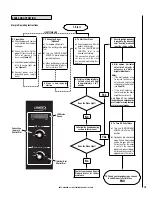
In addition to the standard installation instructions, the following instruc-
tions may be required by local, state or federal building codes:
• Installation should be in accordance with the Manufactured Home and
Safety Standard (HUD), CFR 3280, Part 24.
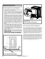
• The stove must be permanently bolted to the floor using 1/4" diameter
lag screws. The lag screws must be an adequate length to extend
through the hearth pad and into the floor as shown in
Figures 8 and 9
.
Install the lag screws as shown in these figures. Two lag screws must
be used.
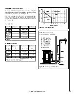
• Connecting the Bella™ stove to outside combustion air is required in
manufactured home installations and when required by local building
codes. An outside air inlet must be provided for combustion and be
unrestricted while unit is in use. Use a galvanized or stainless steel
pipe for the duct (the outside air inlet on the stove is 3” diameter).
The air intake on the exterior of the home should always be located
a minimum of 18" below the flue termination. The Inlet shall remain
free of obstruction while unit is in operation and constructed in a
manner so as to prevent material from dropping into the inlet or into
the area beneath the dwelling. The inlet shall also have a screen with
openings not larger than 1/4" to prevent rodents from entering. See
Figure 21.
• Stove must be permanently electrically grounded to the steel chassis
of the manufactured home using a 8 GA copper wire and a serrated
or star washer (to penetrate paint or protective coating to ensure
grounding). The location selected for ground attachment to the stove
must be dedicated for this purpose. Grounding must comply with
NFPA-70-latest edition standards, CSA C22.1-latest edition in Canada,
as well as any local codes.
• See
Pages 12 through 18
for additional information on venting require-
ments.
• WARNING: DO NOT INSTALL THIS STOVE IN A SLEEPING ROOM IN
A MANUFACTURED HOME.
• CAUTION: THE STRUCTURAL INTEGRITY OF THE MANUFACTURED
HOME FLOOR, WALLS, CEILING/ROOF MUST BE MAINTAINED.
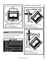
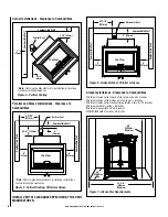
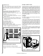
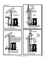
Figure 8 - Manufactured Home Installation
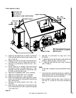
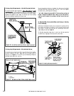
Manufactured Home Exhaust Vent Pipe Installation Guidelines
This stove is approved for venting with Type L and Type PL pellet vent pipe
listed to UL 641 and ULC S609. We recommend the use of venting prod-
ucts manufactured by Security Chimneys International. The pipe should
extend at least 3 feet above the part of the roof through which it passes.
The top of the pipe should be at least 2 feet above the highest required
elevation of any part of the manufactured home within 10 feet of the pipe
(see
Page 14
,
Manufactured Home Chimney Height Requirements
).
If the exhaust vent exits the manufactured home at a location other than
the roof, and exits at a point 7 feet or less above the ground level on which
the manufactured home is position a guard or method of enclosing the
pipe shall be provided at the point of exit for a height of up to 7 feet. The
openings, if any, in this guard shall not allow a 3/4” rod to pass through.
A 1/2” rod could pass through but should not be able to touch the pipe
when inserted through the opening a distance of 4 inches.
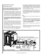
MANUFACTURED HOME INSTALLATION
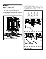
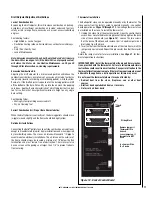
Figure 9 - Manufactured Home Installation
Attach the provided brackets to the stove using a 5/16" bolt. Install lag
screws through the holes in the bottom of the brackets to secure the legs
to the floor as shown here.
Bracket
Lag Screw
Chassis
Floor
Lag Screws
Floor
Protector
Summary of Contents for BELLA
Page 43: ...43 NOTES ...