Page - 14
l
Operate water filtration devices per manufacturer's specifications. Dirty filters can cause a reduction of water flow
to the heat pump. An increase of 7-10 psi (48 to 69 kPa) higher than the clean filter pressure typically reduces
flow rates. This requires the filter to be cleaned or back-washed.
l
Keep baskets free of debris. A large quantity of debris in the pump and skimmer baskets can reduce water flow.
l
Check for improper valve settings. A partially closed valve after the filter, or a full-open bypass around the heat
pump, will cause insufficient water flow through the heat pump.
l
The maximum static pressure (or operating pressure) is 50 psi (345 kPa). These specifications relate to the heat
pump only.
l
Code-specified whole system turnover rates must be satisfied.
1.4.f Adjusting Water Flow Using ΔT (Delta-T)
The Delta-T is the temperature difference between the water temperatures entering and leaving the heat pump.
The equipment can be fine-tuned for maximum performance by balancing water flow rates to maintain an
ideal ∆T.
The adjustment procedure must be completed with the unit in heating mode.
l
Installed temperature ports are required to perform the following procedures.
l
These ports are typically located on the pool in and pool out water lines approximately six inches away from the
heat pump.
PLEASE NOTE -
l
The installation of temperature ports is required for all commercial applications.
l
The installation of temperature ports is strongly recommended for residential installations.
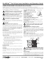
Temperature Port
(Shown with Probe)
1. Adjust the thermostat to its lowest setting with the unit in
heating mode.
2. Deactivate the water filtration pump.
3. Confirm that the filters leading to the heat pump are clean.
4. Adjust the valves controlling water headed towards the heat
pump to the half-open position.
5. Adjust the valves controlling water leading away from the
heat pump to a fully open position.
6. Activate the pool water filtration pump.
7. Slowly raise the thermostat temperature until the heat pump
activates.
l
After a three-minute delay, the heat pump's compressor will start.
8. With the heat pump running, confirm the filtration pump is operating properly with adequate flow and no short
cycling.
9. Wait for water temperatures to stabilize (approximately 5 minutes).
12. Adjust valves in the following order using the temperature chart provided.
a. Adjust the valve that controls water exiting the heat pump until the correct temperature differential is
achieved. Match the temperature measured with a temperature probe to the chart.
b. Wait for water temperatures to stabilize. Then check the temperature again. Re-adjust the valve as needed.
13. Mark valves at these positions for future reference.
1
-
Ins
ta
lla
tion
Summary of Contents for LT1000
Page 2: ......
Page 9: ...Page 6 1 3 Dimensions Leisure Temp LT55 Leisure Temp LT400 1 Installation ...
Page 10: ...Page 7 Leisure Temp LT600 Leisure Temp LT700 LT800 1 Installation ...
Page 25: ...Page 22 Configure Call Flex Enter Installer Menus then proceed 1 Installation ...
Page 29: ...Page 26 1 Installation ...
Page 32: ...Page 29 1 Installation ...
Page 35: ...Page 32 Configure for 24 Hour Mode Enter Installer Menus then proceed 1 Installation ...
Page 36: ...Page 33 Configure for Scheduled Mode Enter Installer Menus then proceed 1 Installation ...
Page 37: ...Page 34 1 Installation ...
Page 40: ...Page 37 1 Installation ...
Page 42: ...Page 39 1 Installation ...
Page 45: ...Page 42 1 Installation ...
Page 48: ...Page 45 1 Installation ...
Page 50: ...Page 47 1 Installation ...
Page 53: ...Page 50 1 Installation ...
Page 55: ...Page 52 1 Installation ...
Page 72: ......