Leister Technologies AG
Galileo-Strasse 10
6056 Kaegiswil/Switzerland
Tel.
+41 41 662 74 74
Fax +41 41 662 74 16
www.leister.com
[email protected]
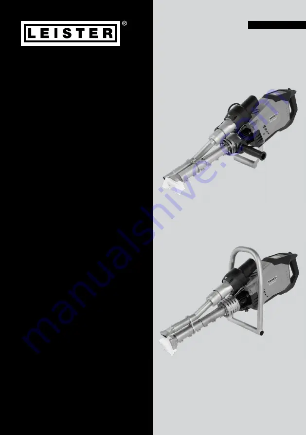
WELDPLAST
600/605
WELDPLAST 605
WELDPLAST 600
English
Page 1: ...Leister Technologies AG Galileo Strasse 10 6056 Kaegiswil Switzerland Tel 41 41 662 74 74 Fax 41 41 662 74 16 www leister com sales leister com WELDPLAST 600 605 WELDPLAST 605 WELDPLAST 600 English...
Page 2: ...ance 15 7 Quick Reference Guide WELDPLAST 600 605 16 7 1 Switching on Starting 16 7 2 Switching off 16 8 The control panel of the WELDPLAST 600 605 17 8 1 Function buttons 17 8 2 Display 18 8 3 Settin...
Page 3: ...10 Accessories 38 11 Maintenance 38 11 1 Lubrication axial groove ball bearing 38 11 2 Cleaning of the filters 38 12 Service and repair 39 13 Training 39 14 Declaration of Conformity 39 15 Disposal 3...
Page 4: ...to life There is a danger to life from electric shock due to electrical voltage The extruder must therefore only be connected to sockets and extension cables with a protective earth conductor Protect...
Page 5: ...any warranty or guarantee claims will be invali dated Welding procedures and types of materials Use the WELDPLAST 600 605 for welding thermoplastic materials based on polyethylene and polypropylene o...
Page 6: ...er W 3680 3680 Frequency Hz 50 60 Temperature C plastic F Air Max 260 Max 300 Air volume 45 100 Drive 60 100 Noise level LpA dB 70 K 3 dB Vibration level ah m s2 2 5 K 1 5 m s2 Weight without power co...
Page 7: ...of loads The weight of your WELDPLAST 600 605 including the transport box is 18 kg 14 kg without transport box The hot air blower 15 and jacket heating 10 must be allowed to cool down sufficiently bef...
Page 8: ...vice s type plate 20 Transfer this information to your operating instructions in the event of any inquiries to our representatives or authorized Leister service center please always refer to this info...
Page 9: ...nection cable 7 Adjustable Handle 8 Device Handle 9 Welding shoe 10 Jacket heating 11 Welding rod entry bilateral 12 Pre heating nozzle 13 Pipe clamp 14 Hot air duct 15 Hot air blower 16 Filter 17 Dri...
Page 10: ...10 33 32 35 32 31 34 30 Figure 1 Control panel 2 30 Button Work light On 50 Off 31 Button Heating On Off 32 Button Reduce Increase 33 Button Confirm 34 Button Menu 35 Display...
Page 11: ...e position of the adjustable handle 7 on the protective tube and fasten it again with a clockwise turn of the adjustable handle 7 Loosen the locking screw 24 adjust the guide handle 23 tighten the loc...
Page 12: ...sive gases Never use the hot air welder extruder in explosive or readily inflammable surroundings Maintain suffi cient distance from combustible materials or explosive gases at all times Place the han...
Page 13: ...r extruder on a suitable surface so that the device is stable and safe Make sure that nothing flammable is radiated by the heat of the extruder Check whether the material to be welded is clean Then ch...
Page 14: ...it stable The preheating nozzle must heat the surfaces to be welded Never feed the welding rod into both welding rod insertion points 11 at the same time Always operate the extruder with the welding...
Page 15: ...the welding shoe hole Switch off the air plastic heaters with the button 31 The cool down mode is activated Note that the jacket heater 10 remains hot for a certain time after the cool down mode has b...
Page 16: ...n the heating with the heating On Off 31 button wait 10 minutes until the desired temperature is reached and the drive is released 4 Guide the welding rod into the welding rod entry point 11 and switc...
Page 17: ...ing the button 33 Button Work light On 50 Off 30 Button Heating On Off 31 Buttons Reducing increasing 32 Press briefly Setting the required setpoint in 5 C or 5 steps Changing the position changing th...
Page 18: ...mple for setting the welding temperature Press the Minus button 32 to select the plastic temperature then press the Confirm button 33 set the desired target temperature value with the Minus Plus butto...
Page 19: ...ess press the Minus Plus button 32 to select the parameters to be adjusted Press the Confirm button 33 then set the desired target value with the Minus Plus button 32 without further input the cursor...
Page 20: ...ss bar indicates current actual value 205 Value to the right of bar 230 indicates setpoint of the selected welding profile or individual setting Temperature too high cool down process Down arrow and p...
Page 21: ...oftware 9 1 Overview menu navigation basic settings Pressing the Menu button 34 takes you to the Basic Settings menu items From the default setting use the Settings menus to access formulas display se...
Page 22: ...Mode see 9 5 Switching on Data Recording see 9 6 Switching off Target and Actual Value Display see 9 4 Switching on Advanced Mode Note Pressing the Menu 34 button will return you to the working displa...
Page 23: ...d Mode 9 2 Overview menu navigation Advanced Mode If you activate Advanced Mode further information and setting options are available WLAN machine settings info mode counter general info warnings Mach...
Page 24: ...24 Warnings see 9 12 Note Pressing the Menu 34 button will return you to the working display in each menu item Switching on Info Mode see 9 9 General info see 9 11 Counter see 9 10...
Page 25: ...33 to accept the recipe Exit the menu by pressing the Menu button 34 Note for test welding appears To edit a name press the Confirm button 33 with the Minus Plus buttons 32 Select characters or digits...
Page 26: ...et the desired value with the Minus Plus 32 buttons Pressing the Confirm 33 button accepts the set value To save the setting use the Minus button 32 select the Save Recipe menu item then press the Con...
Page 27: ...perature is reduced by 30 C In the working display eco mode is displayed with the corresponding symbol The operating state can be reactivated at any time with the drive button 17 or one of the three b...
Page 28: ...Monitored Welding menu item then press the Confirm button 33 If the Audible Alarm is switched on an alarm sounds when the limit value is exceeded To activate the Audible Alarm select the Audible Alar...
Page 29: ...select Seam Naming then press the Confirm button 33 Seam Naming By pressing the Minus button 32 select Seam Naming then press the Confirm button 33 To edit the name press the Confirm button 33 with th...
Page 30: ...ing satellite connection GPS position data are visible by pressing the Minus Plus button 32 The symbol for GPS reception is displayed in the status display 40 If the symbol is filled out in black sate...
Page 31: ...n the menu by pressing the Minus button 32 then press the Confirm 33 button Select the Data Time menu item in the menu by pressing the Minus button 32 then press the Confirm button 33 hour minute year...
Page 32: ...nus 32 button then press the Confirm 33 button Select Switch on work light Select Motor Release Always ON or Always OFF then with the Minus button 32 select the desired unit then press the Confirm but...
Page 33: ...lect the LCD contrast rd menu item in the menu by pressing the Minus button 32 then press the Confirm button 33 press the Minus Plus button 32 the contrast can be set by pressing the Confirm button 33...
Page 34: ...button 33 to reset all settings to the factory settings Remote mode is currently inactive Reset to defaults Remote mode In the menu by pressing the Minus button 32 select the menu item Service Intvl h...
Page 35: ...y utilization in as well as ACTUAL and TARGET temperature in C In the menu by pressing the Minus button 32 Select Info Mode menu item by subsequently pressing the Confirm button 33 activate Info Mode...
Page 36: ...oceeds without delay in the working display Specific information regarding the type of error or the warning can be called up at any time including via the menu Settings under Show Warnings Message typ...
Page 37: ...of Leister Service Center as needed 0002 Undervoltage overvoltage 0004 Hardware error 0008 Thermoelement is defective 0100 Blower is faulty 0200 Communication module error 0400 Drive error Contact Le...
Page 38: ...maintenance or repair work 11 1 Lubrication axial groove ball bearing 11 2 Cleaning the filters 16 After 500h operation of the drive motor the message Maintenance Servicing appears on the control pan...
Page 39: ...ormity Leister Technologies AG Galileo Strasse 10 6056 Kaegiswil Switzerland confirms that this product fulfills the requirements of the following EU Directives in the models that we have made availab...
Page 40: ...by invoice or delivery note manufacturing or pro cessing errors will be rectified by the sales partner through replacement delivery or repair Other guarantee or warranty claims are excluded within th...