background image

GS25, Operation

40

4.4

Working with the RTK Device

Devices fitting into 
the GS25 GNSS 
instrument

Digital cellular phones fitting into the GS25 GNSS instrument

Radios fitting into the GS25 GNSS instrument

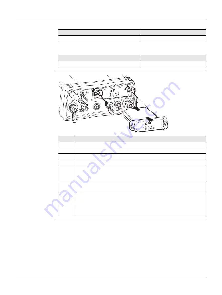
Insert and remove a 
slot-in-device 
step-by-step

Digital cellular phone

Device

Telit UC864-G

SLG1-2

Radio

Device

Satelline M3-TR1, transceive

SLR5-2

Step

Description

1.

Loosen the screws of the compartment cover with the supplied Allen key.

2.

Remove the compartment cover.

3.

Attach the slot-in-device to the compartment cover.

4.

Insert the compartment cover into the compartment (port P3).

5.

Tighten the screws.

All screws have to be tightened to ensure that the instrument is 
waterproof.

6.

Attach the antenna for the slot-in device to RTK device antenna port. Refer 
to "Port PPS".

For the equipment setup as real-time base station with radio, it's recom-
mended to use an external radio antenna mounted on a second tripod. This 
increases the height of the radio antenna and therefore maximises radio 
coverage. Refer to the Leica Viva GNSS Getting Started Guide for detailed 
information about the setup.

P4

E2

P1

E1

GS25_009

1

1

2

3

Summary of Contents for viva GS25

Page 1: ...Leica GS25 User Manual Version 2 0 English...

Page 2: ...f SD 3C LLC All other trademarks are the property of their respective owners Validity of this manual This manual applies to the GS25 GNSS instrument Available documentation Refer to the following reso...

Page 3: ...ur products that are currently in Leica Geosystems Service Centres view the current service status and the expected end date of service mySupport Create new support requests for your products that wil...

Page 4: ...erating Principles 20 3 3 Working with the User Interface 20 3 3 1 Status Functions 20 3 3 2 Configuration 22 3 3 3 Tools 22 4 Operation 24 4 1 Equipment Setup 24 4 1 1 Setting up as a Post Processing...

Page 5: ...aracteristics 47 6 1 2 Accuracy 48 6 1 3 Technical Data 49 6 2 Antennas Technical Data 51 6 3 Conformity to National Regulations 54 6 3 1 GS25 54 6 3 2 SLR5 1 SATEL SATELLINE M3 TR1 55 6 3 3 SLG1 2 Te...

Page 6: ...CAUTION and NOTICE are standardized signal words for iden tifying levels of hazards and risks related to personal injury and property damage For your safety it is important to read and fully understan...

Page 7: ...installations 1 3 Limits of Use Environment Suitable for use in an atmosphere appropriate for permanent human habitation not suitable for use in aggressive or explosive environments DANGER Local safe...

Page 8: ...s occurring if the user does not pay attention to the environmental conditions around for example obstacles excavations or traffic Precautions The person responsible for the product must make all user...

Page 9: ...otected with appro priate protection elements like a lightning arrester These installations must be carried out by an authorised specialist If there is a risk of a thunderstorm or if the equipment is...

Page 10: ...igh ambient temperatures Do not drop or immerse batteries into fluids WARNING If battery terminals are short circuited e g by coming in contact with jewellery keys metalized paper or other metals the...

Page 11: ...oduct meets the strict regulations and standards which are in force in this respect Leica Geosystems cannot completely exclude the possibility that other equipment may be disturbed CAUTION There is a...

Page 12: ...ause disturbances in other equipment in installations in medical devices for example pacemakers or hearing aids and in aircraft It can also affect humans and animals Precautions Although the product m...

Page 13: ...e determined by turning the equipment off and on the user is encouraged to try to correct the interference by one or more of the following measures Reorient or relocate the receiving antenna Increase...

Page 14: ...om the computed ranges to all visible GNSS Global Navigation Satellite System satellites Web server Web based tool to preprogram the GNSS instrument Antenna To receive the satellite signals from the G...

Page 15: ...re covers all functions of the instru ment The Web server application is integrated into the firmware and cannot be deleted The English language is integrated into the firmware and cannot be deleted L...

Page 16: ...g connecting cables or interrupt the power supply when the GS GNSS instrument is switched off SD cards can directly be used in an OMNI drive as supplied by Leica Geosystems Other PC card drives can re...

Page 17: ...ble arm for antennas of devices e Height hook f Cables g Antenna and GAD31 adapter h SD cards SYS13_036 a d e f g h c b a CS15 field controller b GHT62 holder for CS field controller on pole c Allen k...

Page 18: ...instrument is turned on GS25 components 1 2 GS25 components 2 2 A Bluetooth port is included inside the GS25 GNSS instrument to enable connectivity to the CS10 CS15 field controller a Battery compart...

Page 19: ...hile the GS25 is booting all LEDs are lighted Once the GS25 has started the normal LED behaviour starts If GS25 already on Turns off GS25 when held for 3 s All LEDs will shine red for 1 s 2 s and then...

Page 20: ...power down the instrument when exiting SmartWorx Viva software on the CS10 CS15 field controller 3 3 Working with the User Interface Description of the Main Menu functions 3 3 1 Status Functions Descr...

Page 21: ...s and Carte sian coordinates 4 Press the Cancel button to return to the Position menu Step Description 1 Enter the Status menu select Tracking and press the Enter button 2 The current tracking status...

Page 22: ...ion Description Format SD card The format the SD card of the GNSS instrument Format USB device To format a USB device connected to the GNSS instru ment Format System To format the System RAM of the GN...

Page 23: ...button 2 Press the Enter button again to continue with formatting the SD card or press the Cancel button to return directly to the Tools menu 3 Once the formatting of the SD card is completed the GS25...

Page 24: ...ainer during use in high temperatures the lid should be left open Refer to the User Manual for operating and storage temperatures Use an external battery such as GEB171 to ensure operation for a full...

Page 25: ...ons Digital cellular phones can also be used but the setup can differ slightly If the instrument is left in the container during use in high temperatures the lid should be left open Refer to the User...

Page 26: ...rier Screw the GS08plus GS12 GS14 onto the carrier Insert the data storage device and the batteries into the GS14 GS15 6 Check that the tribrach is still level Press the ON OFF button on the instru me...

Page 27: ...the hand strap Refer to the CS10 CS15 User Manual Insert the height hook into the carrier 13 Clip the antenna arm to the GNSS antenna Insert the height hook into the carrier Measure the antenna height...

Page 28: ...r procedures can vary slightly When using the pole with stub ensure that the antenna and the screw to stub adapter slide down the full length of the stub before tightening the locking ring An incorrec...

Page 29: ...the height of the telescopic rod to suit 13 Screw the radio antenna arm onto the telescopic rod 14 Connect the first 1 2 m antenna cable to the radio antenna 15 Pass the cable through the opening in t...

Page 30: ...8 m cable to connect CS field controller and GS instrument c 1 2 m antenna cable to connect radio housing and radio antenna GS_112 c a b Ensures that the antenna pole does not sway around and remains...

Page 31: ...t pouch is designed for carrying an AS05 AS10 antenna when not in use storing coiled cables carrying a non standard radio carrying spare batteries carrying sandwiches GS_103 To half open the backpack...

Page 32: ...eeve to the pole clamp 1 Insert the pole into the clamp hole 2 Attach the holder to the clamp using the clamp bolt 3 Adjust the angle and the height of the holder on the pole to a comfortable position...

Page 33: ...locking pin by pushing the locking pin to the left of the mounting plate 2 Place palm over the top of the CS until fingers grip the bar of the holder underneath 3 Push from the top of the CS toward th...

Page 34: ...are Wizard starts up automatically 5 Check Yes this time only Next 6 Check Install the software automatically Recommended Next The software for Remote NDIS based LGS GS Device will be installed on you...

Page 35: ...displayed under Mobile Devices The folders of the data storage device can be found in StorageCard For PCs with Windows Vista or Windows 7 Windows 8 operating system Windows Mobile Device Center starts...

Page 36: ...iption 1 Start the PC and turn on the GS GNSS instrument Instead of connecting to your PC you can connect your GS GNSS instrument to the Leica CS field controller In this case turn on the Leica CS fie...

Page 37: ...rom 20 C to 55 C 4 F to 131 F Low operating temperatures reduce the capacity that can be drawn high operating temperatures reduce the service life of the battery When the GS25 GNSS instrument is conne...

Page 38: ...de the battery into the battery compartment and push so that it locks into position 4 Close the cover of the battery compartment and tighten the screws 5 To remove the battery loosen the screws to ope...

Page 39: ...Step Description The SD card is inserted in the front of the instrument 1 Loosen the screw on the SD card compartment 2 Open the cover of the SD card compartment 3 Insert the card firmly into the slot...

Page 40: ...rtment cover 3 Attach the slot in device to the compartment cover 4 Insert the compartment cover into the compartment port P3 5 Tighten the screws All screws have to be tightened to ensure that the in...

Page 41: ...of the SIM card slot to eject the SIM card holder 2 Take the SIM card holder out off the SLG1 2 3 Place the SIM card into the SIM card holder the chip facing up 4 Insert the SIM card holder into the...

Page 42: ...rogress red flashing red long break GPRS PDP context activated red long flash short break Packet switched data transfer is in progress off device is off SLR5 2 with Satelline M3 TR1 red the communicat...

Page 43: ...itched off green SD card is inserted flashing yellow SD card is inserted but less than 10 memory left flashing red SD card is inserted but less than 5 memory left red SD card is inserted but full or S...

Page 44: ...int Place the instrument on a tripod or pillar Centred and levelled instrument Centre and level the instrument precisely over the marker flashing green GS25 is in RTK base mode Data is being passed to...

Page 45: ...rson in charge of the product must ensure that the applicable national and international rules and regulations are observed Before transportation or shipping contact your local passenger or freight tr...

Page 46: ...roduct the transport container the foam inserts and the accessories at a temperature not greater than 40 C 104 F and clean them Remove the battery cover and dry the battery compartment Do not repack u...

Page 47: ...s GPS GLONASS Galileo BeiDou Carrier phase and code measurements on L1 L2 and L5 GPS are fully independent with AS on or off Satellites tracked Up to 60 satellites simultaneously on two frequencies Ty...

Page 48: ...asurements The use of multiple GNSS systems can increase accuracy by up to 30 relative to GPS only Differential code The baseline precision of a differential code solution for static and kinematic sur...

Page 49: ...ellites 8000 h L1 L2 L5 data logging at 15 s rate 32000 h L1 L2 L5 data logging at 60 s rate 1440000 real time points with codes GPS GLONASS 12 8 satellites 6800 h data logging at 15 s rate 27200 h da...

Page 50: ...1176 45 MHz Galileo E5b 1207 14 MHz Galileo Alt BOC 1191 795 MHz BeiDou B1 1561 098 MHz BeiDou B2 1207 14 MHz Gain Typically 27 dBi Noise Figure Typically 2 dBi Type Operating temperature C Storage t...

Page 51: ...ane With GS05 GS06 or GS10 GS25 AS10 GPS GLONASS Galileo BeiDou SmartTrack antenna with built in ground plane With GS10 GS25 AR10 GPS GLONASS Galileo BeiDou antenna with large ground plane and built i...

Page 52: ...2 V DC Current 35 mA typ 35 mA typ 100 mA max 100 mA max 100 mA max Frequency GPS L1 1575 42 MHz GPS L2 1227 60 MHz GPS L5 1176 45 MHz GLONASS L1 1602 5625 1611 5 MHz GLONASS L2 1246 4375 1254 3 MHz G...

Page 53: ...EC 60529 Dust tight Protected against water jets Protected against continuous immersion in water Tested for 2 h in 1 40 m depth AR10 AR20 AR25 IP67 IEC 60529 Dust tight Protected against water jets Wa...

Page 54: ...ntial requirements and other relevant provisions of Directive 1999 5 EC The declaration of conformity can be consulted at http www leica geosystems com ce Class 1 equipment according European Directiv...

Page 55: ...ance with the essential requirements and other relevant provisions of Directive 1999 5 EC The declaration of conformity can be consulted at http www leica geosystems com ce Class 2 equipment according...

Page 56: ...1999 5 EC The declaration of conformity may be consulted at http www leica geosys tems com ce Class 1 equipment according European Directive 1999 5 EC R TTE can be placed on the market and be put into...

Page 57: ...he Leica Geosystems Soft ware Licence Agreement Such agreement is provided together with all products and can also be referred to and downloaded at the Leica Geosystems home page at http www leica geo...

Page 58: ...interface in out 8 pin LEMO h Port 3 Communication slot in port and LEDs i Port PWR Power in 5 pin LEMO j Communication Slot in port Antenna TNC GS25_001 b e f h g i j c d a P2 P4 E2 E1 P1 1 7 6 8 5...

Page 59: ...cation pin In or out 15 GPIO General purpose signal In or out A1 NC Not used A2 RF1 Antenna port radio to antenna 1 7 6 8 5 4 3 2 PIN_003 Pin Signal Name Function Direction 1 RTS RS232 ready to send O...

Page 60: ...systems AG Heinrich Wild Strasse CH 9435 Heerbrugg Switzerland Phone 41 71 727 31 31 www leica geosystems com 793206 2 0 0en Original text Printed in Switzerland 2014 Leica Geosystems AG Heerbrugg Swi...

Reviews: