background image

Control unit with touch panel

42 

ARveo / Ref. 10 747 384 / Version 04

9  Control unit with touch 

panel

NOTE
Damage to the touch panel.


X

Operate the touch panel using your fingers only. 
Never use hard, sharp or pointy objects made out of wood, 
metal or plastic.


X

Never clean the touch panel using cleaners that contain abrasive 
substances. These substances can scratch the surface and cause 
it to be become dull.

9.1  Menu structure

1

2

3

4

5

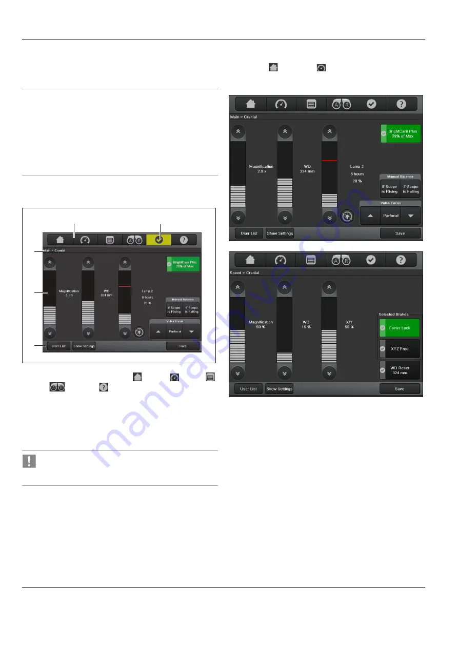
1  Quick access to the screens "Main"  , "Speed"  , "Menu"   

"DIC" 

 and "Help" 

2  Status line
3  Display range
4  Dynamic button bar
5  Warning messages

In operational mode, the status line displays the current 
user and specifies the current location in the menu at all 
times.

9.2  Selecting users

In the "Main"   and "Speed"   menu screens, the two buttons 
"User List" and "Show Settings" appear in the dynamic button bar 
at all times.

Summary of Contents for ARveo

Page 1: ...MEDICAL DIVISION User Manual 10 747 384 Version 04 ARveo...

Page 2: ...Heerbrugg Tel 41 71 726 3333 Legal disclaimer All specifications are subject to change without notice The information provided by this manual is directly related to the operation of the equipment Medi...

Page 3: ...ope on 34 8 2 Positioning the microscope 35 8 3 Adjusting the microscope 35 8 4 Transport position 41 8 5 Shutting down the surgical microscope 41 9 Control unit with touch panel 42 9 1 Menu structure...

Page 4: ...e Indicates a potentially hazardous situation or improper use which if not avoided may result in appreciable material financial and environmental damage Information about use that helps the user to em...

Page 5: ...d messages X Allocate responsibilities for commissioning operation and maintenance Monitor compliance with this X Only use the ARveo surgical microscope when it is free of defects X Inform your Leica...

Page 6: ...ly hazardous optical infrared and UV radiation X Do not look at the operating lamp X Minimize exposure to eyes or skin X Use appropriate shielding WARNING Danger of burn injuries in otologic surgery X...

Page 7: ...efore attaching the sterile drape check the counterweights for correct seating CAUTION Risk of infection X Leave sufficient space around the stand to ensure that the sterile drape does not come into c...

Page 8: ...Safety notes 6 ARveo Ref 10 747 384 Version 04 3 5 Signs and labels 1 2 3 15 14 9 8 7 11 4 A 6 5 16 17 12 A 10 10 13...

Page 9: ...Warning of hot surface 11 RISK GROUP 3 WARNING IR emitting from this product Do not look at operating lamp WARNING Possibly hazardous optical radiation emitted from this product Do not look at operati...

Page 10: ...Safety notes 8 ARveo Ref 10 747 384 Version 04 1 2 3 5 2 4 2 2 1 Monitor weight label 2 Warning sign for squeezing hands or fingers 3 For installation only 4...

Page 11: ...o stand 1 2 3 4 5 6 7 8 9 10 1 Arm system 2 Tension rod 3 Video monitor optional 4 Control unit with touch panel 5 Suspension device for footswitch 6 Illumination unit 7 Base 8 Interface panel 9 Lock...

Page 12: ...17 9 Lock for installation only 11 Vertical arm 12 Interface panel 13 Footbrake 14 Handrail 15 Monitor arm 16 Camera control unit optional 17 Recording unit optional With its open architecture the AR...

Page 13: ...visible light Leica HD C100 optional Interface for assistants either to the left and right side or to the back Main surgeon and back assistant interface 360 rotatable both Back assistant interface wit...

Page 14: ...ier Leica M530 two directions of movement are balanced A and B 4 5 The essential performance of the ARveo is Providing sufficient light to the situs and to guarantee mechanical locking of the optics c...

Page 15: ...rgical microscope 5 In the rotary joint 6 Brakes are operated via handle or footswitch if used The button of a handle footswitch with the assigned function Selected Brakes refer also to the chapter on...

Page 16: ...225 mm Ev light intensity Iv brightness d distance from light source This means that less light is required to work with the microscope at a shorter distance than at a greater distance It is advisabl...

Page 17: ...ing aid Leica SpeedSpot If Leica SpeedSpot is activated for the current user see page 49 the focussing aid is released when the brakes are released or when focussing Two convergent light beams meet ex...

Page 18: ...agnification 8 Leica M530 Optics carrier 9 Switch for manual balancing of the A carriage 10 A carriage 11 Handle clamping lever 12 Switch for manual balancing of the B carriage 13 B carriage 14 Micros...

Page 19: ...osystems Schweiz AG may be connected here AD F 1 and 2 are digital relay outputs that can switch 24 V 2 A 9 10 11 12 13 14 15 16 17 18 19 20 8 8 not in use 9 camera input optional 10 BNC IN 2x 11 BNC...

Page 20: ...a Microsystems Schweiz AG may be connected here External Monitor Interface panel stand Ferrite 1 Ferrite 2 Ferrite 2 Ferrite 1 Requirements regarding EMC To reduce emission and ensure EMC compatibilit...

Page 21: ...connecting the ARveo to an equipotential bonding device This is part of the customer s building installation Observe the requirements of EN 60601 1 8 6 7 7 Fuse box flap 9 10 8 Lamp inserts for main i...

Page 22: ...brakes You can assign switches 1 2 3 and 5 of the handles individually for each user in the configuration menu In all presets key 4 releases all brakes This key cannot be configured For the joystick...

Page 23: ...14 functions crosswise Footswitch 12 functions lengthwise Footswitch 16 functions lengthwise Footswitch 16 functions crosswise Footswitches can be assigned individually for each user in the configurat...

Page 24: ...never pull it CAUTION Surgical microscope can move without warning X Always lock the footbrake when you are not moving the system NOTE Damage to the ARveo surgical microscope during transportation X N...

Page 25: ...ever carry out the intraoperative AC BC balancing above the patient X Make sure that the optical accessories are clean and free of dust and dirt 7 3 Setting the binocular tube 7 3 1 Setting the interp...

Page 26: ...he lens at working distance X Focus the microscope X Set the maximum magnification X Focus the microscope X Set the minimum magnification X Without looking into the eyepieces turn both eye lenses to 5...

Page 27: ...the accessories or attempt to rebalance the microscope while it is above the field of operation X Balance the ARveo after re equipping it X Do not release the brakes when the instrument is in an unba...

Page 28: ...on the control unit During the balancing procedure the push button flashes green and an acoustic signal sounds can be deactivated in the service menu 2 The following dialog window appears on the touc...

Page 29: ...lancing push button on the control unit again During the balancing procedure the push button flashes yellow and an acoustic signal sounds can be deactivated in the service menu The following dialog wi...

Page 30: ...irection 3 A direction Make sure no accessories collide with the microscope during manual balancing X Check the balancing X Press the All Brakes button on the handle Optics carrier tilting to the righ...

Page 31: ...mize the position of the side assistant 7 6 3 Correcting the D balancing manually The internal weight 1 in the stand compensates for the weight of the surgical microscope and the installed accessories...

Page 32: ...e to falling weight disk or cover X When changing the weight disk make sure that your feet are not beneath the weight disk or the cover X Detach the cover 3 from the axis 3 X Unscrew the hexagonal nut...

Page 33: ...tion first swing the microscope away from the operating field X Never carry out the intraoperative AC BC balancing above the patient The ARveo can be positioned easily on the operating table and offer...

Page 34: ...ries section CAUTION Risk of infection X Leave sufficient space around the stand to ensure that the sterile drape does not come into contact with non sterile components CAUTION Danger of injury due to...

Page 35: ...d protective glass on the optics carrier so that the markings on the Leica M530 1 and on the protective glass 2 are aligned a b 1 2 X Insert the protective glass upwards into the bayonet mount in dire...

Page 36: ...y X Adjust the field of view to match the operating field X Irrigate the wound frequently X Cover the exposed parts of the pinna with a moist surgical sponge X Connect the microscope to a grounded soc...

Page 37: ...nel monitor a hand footswitch or handle On the touch panel monitor in the Main menu screen X Press the or button on the bar for adjusting the brightness of the illumination or X Press the brightness a...

Page 38: ...rightness is reduced automatically It is advisable to begin with a low light output and increase the light intensity until an optimum level of illumination is achieved When shipped from the factory th...

Page 39: ...rms you when the xenon lamp is losing luminosity and is no longer sufficient either for blue light FL400 application only or for white light all other applications We recommend that you keep a replace...

Page 40: ...duced in order to protect the tissue If the field diameter is locked in a small position and cannot be adjusted either automatically or manually you can use an OR lamp to better illuminate a large fie...

Page 41: ...e X When using lasers always set the working distance of the microscope to laser distance and lock the microscope in position X Do not adjust the rotary button for manual setting of the working distan...

Page 42: ...Setting the working distance manually WARNING Danger of serious damage to tissue due to incorrect working distance X When using lasers always set the working distance of the microscope to laser dista...

Page 43: ...l observers with zero diopters respectively with correct individual diopter settings This command can be as well given on the GUI and from the handle if defined 8 4 Transport position X Press the All...

Page 44: ...sive substances These substances can scratch the surface and cause it to be become dull 9 1 Menu structure 1 2 3 4 5 1 Quick access to the screens Main Speed Menu DIC and Help 2 Status line 3 Display...

Page 45: ...familiarize yourself with the assignment of the handles and the optional footswitch if used 9 2 2 Presets You can find a list of default users preset by Leica for the most common types of operation un...

Page 46: ...he operational menu If you want to keep the current settings you can save them by clicking the Save button which appears as soon as the basic settings of the current users have been changed either for...

Page 47: ...ain X Choose Save as current and enter the password PIN again If no password PIN was defined you can define a password PIN 4 10 characters X Press OK for re entering and confirmation If the re entered...

Page 48: ...or each user in the user settings when All Brakes are released This function is deactivated in the factory default configuration 9 3 3 Setting the Speed start values For the selected user you can set...

Page 49: ...croll forwards or backwards in the list by clicking the arrowheads X In the left selection field select the function group with the desired functions X You can scroll forwards or backwards in the list...

Page 50: ...ft selection field select the function group with the desired functions You can scroll forwards or backwards in the list by clicking the arrowheads X Select the desired function X Click a free caption...

Page 51: ...manuals 9 3 9 AutoFocus Settings AutoFocus is an optional function and can be ordered additionally AutoFocus is not available in all countries AutoFocus is not available with FL800 mode and FL400 mod...

Page 52: ...entered 9 4 Menu Maintenance menu X Press the Menu button and select Maintenance The Maintenance menu offers the following screens Lamp History Check Switches Microscope Settings 9 4 1 Maintenance Lam...

Page 53: ...le you want to test If the key you have pressed is functioning properly a green dot appears on it on the display The comment Tested appears in the caption field of the key 9 4 3 Maintenance Microscope...

Page 54: ...gical microscope X Press the button for the topic desired Detailed information How to is displayed The Help button in the static menu bar provides access to the How To screens at all times 9 6 Menu Se...

Page 55: ...ube var 0 180 T Type II Binocular tube var 30 150 T Type II L Inclined binocular tube T Type II Straight binocular tube T Type II Inclined binocular tube 45 Type II Eyepiece 10 Eyepiece 12 5 Eyepiece...

Page 56: ...Footswitches Wireless Footswitch 14 functions Wireless Footswitch 12 functions Cart ITD for 31 and 55 Monitor See the corresponding instruction for use Do not use third party products without premissi...

Page 57: ...on the following active ingredients aldehydes alcohols quaternary ammonium compounds Due to potential damage to the materials never use products based on halogen splitting compounds strong organic aci...

Page 58: ...enance contract with them It is recommended to conclude a service contract with Leica Service Use only original spare parts for servicing After 18 months you will be reminded that the inspection is du...

Page 59: ...row 4 is pointing to the left X Close the access door again The illumination push button item 2 section 6 2 lights up green Whenever you replace a bulb reset the bulb s hour meter to 0 by double click...

Page 60: ...ol may also be used to clean the optics if heavy contamination such as fingerprints grease streaks etc is present X Dry off products except for optical components with a disposable cloth paper cloth D...

Page 61: ...nsion 10446058 Protective glass multifocal lense 10448439 Protective glass 10448440 Cover sterilizable 10448431 Protective objective glass 10448296 Protective objective glass spare part package of 10...

Page 62: ...ect X Check selection of the assistant see page 25 The image remains unfocused Eyepieces are not mounted correctly X Screw the eyepieces all the way on Diopters not set correctly X Perform dioptric co...

Page 63: ...tall the video camera ARveo is not correctly balanced Position of accessory was changed after balancing X Balance out ARveo see page 25 X Perform intraoperative AC BC balancing see page 28 ARveo canno...

Page 64: ...connecting cable has been disconnected or is defective X Check corresponding connection cable for proper seating and function X Contact your Leica representative Rear load too high The accessories be...

Page 65: ...tics carrier Objective working distance 225 600 mm motorized multifocal lens continuously adjustable manual adjustment option status displayed in the display of the optics carrier Eyepieces Wide field...

Page 66: ...Binocular tube Focal length Art No Type A f162 66 10447701 10446575 10448088 10446574 10446587 10446618 Type B f170 0 10446797 10448159 10448217 not recommended 14 2 3 Microscope carrier Rotation of...

Page 67: ...the camera image size with respect to the field of view for the visual video camera Please be aware that the field of view is not fully covered by the documentation system 14 2 4 IGS Interface Compat...

Page 68: ...lumination system and built in automatic lamp quick changer Control elements Pistol handle with 10 functions for magnification working distance All Brakes button releases 6 brakes side knob releases s...

Page 69: ...471 EN 980 The Medical Division within Leica Microsystems Schweiz AG hold the management system certificates for the international standard ISO 13485 relating to quality management quality assurance a...

Page 70: ...3 4 2 1 Leica M530 Optics carrier 2 Leica ULT530 or GLOW800 or Leica FL800 ULT 3 Leica ULT530 or GLOW800 or Leica FL800 ULT 4 Leica FL400 FL560 5 CaptiView Optional Side assistant Magnification Multip...

Page 71: ...kg 10448088 S Binocular tube var 0 180 T Type II Not recommended vignetting 1 42 kg M Binoculartubeforbackassistant 10446797 S Binocular tube var 30 150 T Type II L Recommended 0 81 kg 10448088 S Bin...

Page 72: ...eces main back sides 10448028 O Eyepiece 10x 2 eyepieces per binocular tube 0 10 kg 10448125 O Eyepiece 8 3x 0 10 kg 10443739 O Eyepiece 12 5x 0 10 kg 10448245 O Mouth switch 0 22 kg 10446058 O Protec...

Page 73: ...Specifications ARveo Ref 10 747 384 Version 04 71 14 7 Dimensional drawings Dimensions in mm...

Page 74: ...Specifications 72 ARveo Ref 10 747 384 Version 04 1200 max 1925 720 x 720 2685 1945 Dimensions in mm...

Page 75: ...Specifications ARveo Ref 10 747 384 Version 04 73 1180 1785 430...

Page 76: ...electromagnetic emissions The ARveo surgical microscope is intended for operation in an environment as specified below The customer or the user of the ARveo surgical microscope should make sure that i...

Page 77: ...000 4 4 2 kV for power supply line 1 kV for input and output lines 2 kV for power supply line 1 kV for input and output lines Mains power quality should be that of a typical commercial or hospital env...

Page 78: ...P in m 800 MHz up to 2 5 GHz d 2 4 P in m 0 01 0 24 0 24 0 24 0 1 0 8 0 8 0 8 1 2 4 2 4 2 4 10 8 0 8 0 8 0 100 24 0 24 0 24 0 For transmitters rated at a maximum output power not listed above the reco...

Page 79: ...ing 5 Function check X Check the fiber optics cable connection to the optics carrier X Connect the power cable X Switch on the microscope X Switch on the illuminator at the control unit X Leave the il...

Page 80: ...CH 9435Heerbrugg 2020 Printed 11 2020 Subjecttomodifications LEICAandtheLeicaLogoare registeredtrademarksofLeicaMicrosystemsIRGmbH Leica Microsystems Schweiz AG Max Schmidheiny Strasse 201 CH 9435 He...

Reviews: