LEGRAND Wattstopper LMDC-100 Manual Download Page 3

3

SETTING SENSOR PARAMETERS

To adjust the default sensor parameter settings:

1.  Remove the cover to expose the CONFIGURE and LOAD buttons.

2.  Press the CONFIGURE button 3, 4, or 5 times to choose the setting to 

adjust (see the chart below). The button must be pressed the desired 

number of times within a 5 second period. 

3.  Three seconds after successfully selecting a configuration setting, the 

red and blue LEDs will blink until exiting Configuration mode. 

NOTE: 

While in Configuration mode, the 

red LED

 blinks 

corresponding to the currently selected parameter (3, 4, or 

5 times), and 

blue LED

 blinks corresponding to the current 

value of that parameter (1 through 10 times). (For PIR and 

Ultrasonic Sensitivity, if the blue LED does not blink, that 

parameter is currently set to OFF.)

4.  Press the LOAD button to change the value for that setting based 

on the values in the following chart. Each time you press the Load 

Button, it will advance to the next value and the number of times the 

Blue LED blinks will change to show the new value. After reaching the 

maximum value (six presses for Time Delay and eleven presses for 

PIR and Ultrasonic Sensitivity), a subsequent button press will wrap back to the one button press value.

NOTE: 

When you 

first

 press the LOAD button after selecting the parameter to edit, the number of initial button presses will go 

directly to that value. So for example, if Time Delay is currently at 20 minutes and you press the LOAD button twice, it will 

change to 10 minutes, 

not

 increase by two to 30 minutes. After that, each additional button press increases the value.

5.  To return to normal operation, press the CONFIGURE button the number of times corresponding to the currently selected setting 

(3, 4, or 5 times), also indicated by the red LED blink pattern.

NOTE: 

You must press the CONFIGURE button the same number of times to exit edit mode. For example, if you press the button 

4 times to edit PIR Sensitivity, pressing 3 times will 

not 

exit edit mode.

After exiting edit mode, you may repeat from step 2 to edit additional parameters.

Red LED

PIR Detect

& Push n’ Learn

Blue LED

Ultrasonic Detect

Load Binding

Load

Configure

www.legrand.us/wattstopper
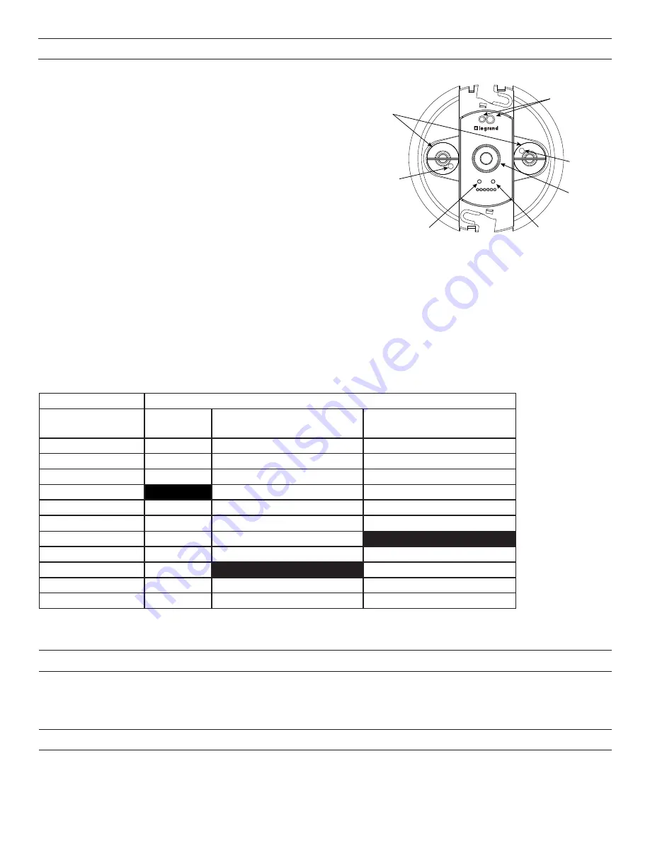
Red LED

Blue LED

Configure Button

Load Button

IR Transmitter

and Receiver

Ultrasonic

Sensors

PIR Sensor

Configure Button Presses (Red LED)

Load Button Presses

(Blue LED)

3 Presses

Time Delay

4 Presses

PIR Sensitivity

5 Presses

Ultrasonic Sensitivity

1 Press

5 minutes

10%

10%

2 Presses

10 minutes

20%

20%

3 Presses

15 minutes

30%

30%

4 Presses

20 minutes

40%

40%

5 Presses

25 minutes

50%

50%

6 Presses

30 minutes

60%

60%

7 Presses

70%

70%

8 Presses

80%

80%

9 Presses

90%

90%

10 Presses

100%

100%

11 Presses

0% (Off) – Blue LED will not blink 0% (Off) –  Blue LED will not blink

Default Values Highlighted

ENTERING TEST MODE

Test Mode allows you to quickly determine the coverage area of the LMDC-100 by setting Time Delay to 5 seconds. You can then move 

around till the sensor triggers the lights, then move out of range and wait 5 seconds (or until the lights turn Off) before trying again.
To turn Test Mode On, press and hold the LOAD button for 3 to 10 seconds The red LED will turn on. To exit Test Mode, press and hold 

the LOAD button for 3 to 10 seconds again.

RESETTING THE LMDC-100

To reset the LMDC-100, press and hold the LOAD button for 10 to 20 seconds. Both the red and blue LEDs will turn on. Once you 

release the button, the LMDC-100 will reset to default values.
If you press and hold the LOAD button for more than 20 seconds, the red LED will turn on and the blue LED will blink. All wired sensors 

in the room will reset to default values.

Summary of Contents for Wattstopper LMDC-100

Page 1: ...attstopper room controllers and also available at www legrand us wattstopper Installation shall be in accordance with all applicable regulations local and NEC codes Wire connections shall be rated suitable for the wire size lead and building wiring employed For Class 2 DLM devices and device wiring To be connected to a Class 2 power source only Do not reclassify and install as Class 1 or Power and...

Page 2: ... ceiling tile WARNING A junction box used for sensor installation must not contain any Class 1 Class 3 or other power or lighting line voltage circuits CONNECTIVITY The illustrations below show examples of free topology wiring The LMDC 100 communicates to all other Digital Lighting Management devices connected to the low voltage DLM Local Network regardless of their position on the DLM Local Netwo...

Page 3: ...y selected setting 3 4 or 5 times also indicated by the red LED blink pattern NOTE You must press the CONFIGURE button the same number of times to exit edit mode For example if you press the button 4 times to edit PIR Sensitivity pressing 3 times will not exit edit mode After exiting edit mode you may repeat from step 2 to edit additional parameters Red LED PIR Detect Push n Learn Blue LED Ultraso...

Page 4: ...2 Check for 24VDC input to the sensor Plug in a different DLM device at the sensor location If the device does not power up 24VDC is not present Check the high voltage connections to the room controller If high voltage connections are good and high voltage is present recheck DLM local Network connections between the sensor and the room controller The wrong lights are controlled 1 Configure the sen...

Page 5: ...e 1 ou en tant que fil d alimentation ou d éclairage Ce dispositif est conforme à la section 15 des règlements de la FCC On peut s en servir sous réserve des deux conditiond suivantes 1 Ce dispositif ne provoque pas d interférences nuisibles 2 Il doit être en mesure d accepter toute interférence reçue y compris les interférences qui peuvent causer un fonctionnement indésirable REMARQUE Ce matériel...

Page 6: ... neutre Câble rouge vers charge A 1 Câble jaune vers charge B 2 LMRC 102 Régulateur d ambiance Boîte de jonction Détecteur de présence monté au plafond Interrupteur Vers charge Partie arrière 10cm Octogonale Boîte de jonction au moins 4cm de profondeur Couvercle frontal Plafond Trou percé au plafond Câble LMRJ Câble LMRJ Clips ressort 2 Vis Pour les applications exigeant le respect des normes plén...

Page 7: ...0 minutes et n augmentera pas de deux à 30 minutes Après cela chaque pression supplémentaire sur un bouton augmente la valeur 5 Pour revenir au fonctionnement normal appuyez sur le bouton CONFIGURER le nombre de fois correspondant au réglage actuellement sélectionné 3 4 ou 5 fois également indiqué par le motif de clignotement de la DEL rouge REMARQUE Vous devez appuyer sur le bouton CONFIGURE le m...

Page 8: ...ambiance Si les raccords haute tension sont corrects et que la haute tension passe bien vérifier de nouveau les branchements au réseau DLM local entre le capteur et le régulateur d ambiance Les éclairages pilotés ne sont pas les bons 1 Configurer le capteur pour qu il pilote les éclairages souhaités à l aide de la procédure de réglage Push n Learn Les LED s allument et s éteignent mais la charge n...

Page 9: ...tale como Clase 1 ni con circuitos de alimentación e iluminación Este dispositivo cumple con la parte 15 de las reglas de la FCC La Operación está sujeta a las dos condiciones siguientes 1 Este dispositivo no puede causar interferencias perjuduciales y 2 este dispositivo debe aceptar cualquier interferencia recibida incluidas las interferencias que puedan causar una operación no deseada NOTA Este ...

Page 10: ...Blanco Cable neutro Cable rojo a carga A 1 Cable amarillo a carga B 2 LMRC 102 Controlador de habitación Caja de conexiones Sensor de ocupación de montaje en techo Interruptor Hacia la carga Alojamiento trasero 10cm Caja Octogonal de conexiones al menos 4cm de profundidad Cubierta frontal Cielo raso Orificio de techo Cable LMRJ Cable LMRJ Abrazaderas de resorte 2 Tornillos Para aplicaciones que re...

Page 11: ...LOAD dos veces cambiará a 10 minutos no aumentará en dos a 30 minutos Después de eso cada vez que se presiona un botón adicional aumenta el valor 5 Para volver al funcionamiento normal presione el botón CONFIGURE el número de veces que corresponda al ajuste seleccionado actualmente 3 4 o 5 veces también indicado por el patrón de parpadeo del LED rojo NOTA Debe presionar el botón CONFIGURE la misma...

Page 12: ...C al sensor Conecte un dispositivo DLM diferente en la ubicación del sensor Si el dispositivo no se enciende los 24 V de CC no están presentes Revise las conexiones de alto voltaje al controlador de la habitación Si las conexiones de alto voltaje son correctas y hay alto voltaje vuelva a revisar las conexiones de red local DLM entre el sensor y el controlador de la habitación Se controlan las luce...

Reviews: