37
KEOR T
Installa
tion M
anual
Double check the polarity of battery connection!
Make sure that all circuit breakers are at “OFF” position before
starting with the installation.
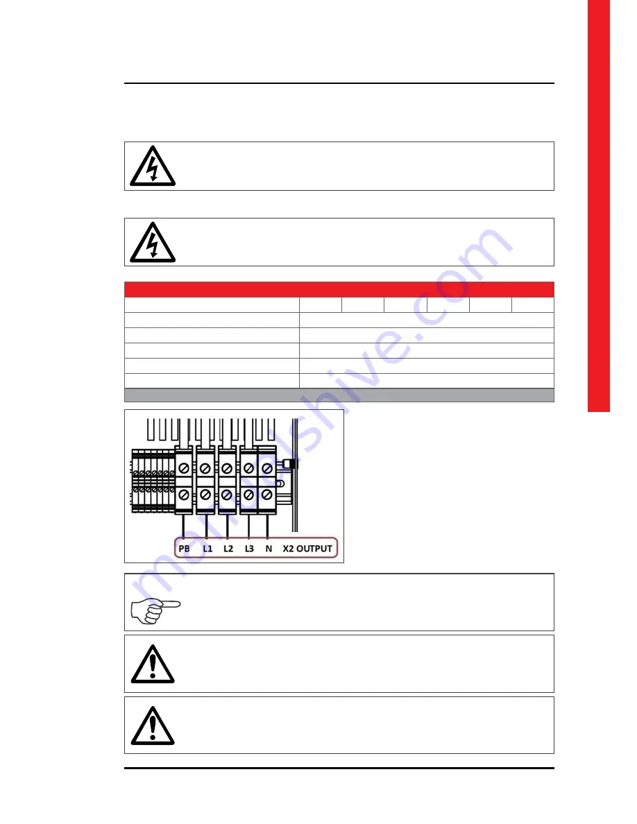
Connect the phase cable to X2 OUTPUT: X2/L1 –
X2/L2 – X2/L3 terminal and the neutral cable to
X2 OUTPUT: X2/N terminal. Neutral connection
should be done directly.
To enable the short circuit protection feature of the UPS, each load should be supplied
through a separate circuit breaker chosen according to the load current. This may pro-
vide quick disconnection of the short circuited load and maintain operation continuity
of the other loads.
Each load should be supplied through separate circuit breaker and the cable cross
section should be chosen according to the load current value.
Make sure that the UPS is not overloaded to provide a higher quality supply to the
loads.
5.3.1.5.
Output Connection
Electrical Characteristics - Inverter
Model (kVA)
10
15
20
30
40
60
Rated output voltage (selectable) (V)
400 3Ph + N (380/415 configurable)
Output voltage tolerance
static load ±1%, dynamic load VF-SS-111 compliant
Rated output frequency (Hz)
50/60 Hz (selectable)
Autonomous frequency tolerance
±0.02% on mains power failure
Harmonic voltage distortion
< 2% with linear load, < 4% with non linear load
Table.7
Summary of Contents for KEOR T
Page 1: ...KEOR T Installation Manual LE07544AA ...
Page 2: ...2 KEOR T ENGLISH 6 EN ...
Page 5: ...5 KEOR T Installation Manual Battery Fast Fuses Installation Operating Manuals ...
Page 32: ...32 Figure 5 3 1 4 1 Keor T 10 30kVA 1x60pcs 7 9Ah BATTERY WIRING DIAGRAM ...
Page 34: ...34 Figure 5 3 1 4 3 Keor T 40 60kVA 2x60pcs 7 9Ah BATTERY WIRING DIAGRAM ...
Page 50: ...50 SEPARATED RECTIFIER AND BYPASS INPUTS ...
Page 51: ...51 KEOR T Installation Manual COMMON RECTIFIER AND BYPASS INPUTS ...


