background image

20

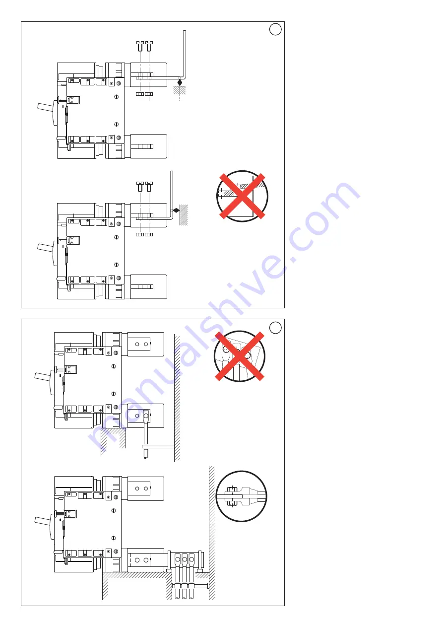
Connection du chassis débrochable 
Important:

la connection prise arriére ne doit pas

supporter les efforts mécaniques des cables ou
des barres qui y sont raccordés. Le raccordement
doit se faire de sorte à pouvoir supporter l'effort
électromécanique d'un court-circuit. Pour les
distances voir le guide mise en oeuvre de la
puissance.

Connections to the c.b. and fixation
Important:

the terminals of the c.b. are only

electrical connections and cannot be used as
support of cables or bars. Therefore, cables and
bars must be properly secured, to hold the
electrodinamic forces. For the cables and bars
support distances, see the Guide for the panel
installation.

Anschluss an den Schalter und Befestigung
Wichtig:

die Endteile des Schalters sind nur

elektrische Anschlüsse und dürfen nicht als Kabel-
oder Schienenhalterungen verwendet werden.
Folglich müssen die Kabel und Schienen richtig
befestigt werden, um die elektrodynamischen
Kräfte ertragen zu können. Für die Maße der
Schienen und Kabel, beziehen Sie sich bitte auf
die Installationsanweisungen der Tafel.

Conexiones al interruptor y anclajes
Importante:

los terminales son sólo órganos de

conexiones y no se deben utilizar para sostener
cables o barras. Por lo tanto, fije las barras y/o
cables correctamente para soportar los esfuerzos
electrodinámicos. Para las distancias de anclaje,
véase la Guía técnica para el sistema de baja
tensión.

Collegamento all’interruttore e fissaggio
Importante:

i terminali dell’interruttore sono

solamente collegamenti elettrici e non possono
essere usati come supporto dei cavi o delle barre.
Di conseguenza, i cavi e le barre devono essere
fissate adeguatamente in modo tale da tenere le
forze elettrodinamiche. Per le distanze dei cavi e
barre, fare riferimento alla Guida per l'installazione
del pannello.

Conexões ao disjuntor e montagem
Importante:

as tomadas do disjuntor são somente

conexões eléctricas e não podem ser usadas
como suporte de cabos ou barras. Então, os cabos
e as barras devem ser fixadas adequadamente,
para suportar as forças electrodinâmicas. Para as
distâncias dos suportes dos cabos e das barras
ver as instruções para a instalação do painel.

Gjlrk.xtybt r dsrk.xfntk. b pfrhtgktybt

Df;yj

!

Hfp]tvs dsrk.xfntkz cke;fn njkmrj

lkz gjlrk.xtybz 'ktrnhbxtcrb[ wtgtq b yt

ljk;ys ytcnb yf ct,t dtc  ghjdjljd bkb infyu7

Bp 'njuj cktletn6 xnj ghjdjlf b infyub

ljk;ys ,snm pfrhtgktys yflkt;fobv j,hfpjv

nfr6 xnj,s jyb ,skb d cjcnjzybb dslth;bdfnm

'ktrnhjvfuybnyst yfuheprb7 

Hfccnjzybz vt;le ghjdjlfvb b infyufvb

erfpfys d Herjdjlcndt gj vjynf;e gfytkb7

Podłączenie do wyłącznika i umocowanie
Uwaga:

zaciski wyłącznika są połączeniami

wyłącznie elektrycznymi i nie mogą być używane
jako wsporniki dla kabli lub drążków. W związku z
tym, kable i drążki muszą zostać odpowiednio
umocowane, tak aby wytrzymały siły
elektrodynamiczne. W przypadku odległości kabli i
drążków, należy się odnieść do Instrukcji instalacji
płyty.

Devre kesici anahtara ba¤lantı ve sabitleme
Önemli:

devre kesici anahtar terminalleri salt

elektrik ba¤lantılardır ve kablo veya bar destekleri
olarak kullanılamazlar. Bu do¤rultuda, kablo lar ve
barlar, elektrodinamik güçleri kaldırabi lecek flekilde
uygun sabitlenmelidirler. Kablo ve barların mesa
feleri için, panel kurul masına dair Kılavuzu
referans alın. 

30

31

Summary of Contents for DPX

Page 1: ... broflürü 02 2009 01 GF Y3466A Disjoncteurs débrochables Draw out circuit breakers Herausnehmbare Selbstschalter Interruptores automáticos extraíbles Interruttori automatici estraibili Disjuntores extraíveis C tvyst fdnjvfnbxtcrbt dsrk xfntkb Wyłączniki samoczynne wysuwane Çekmeli otomatik devre kesici anahtarlar DPX 1250 DPX 1600 DPX I 1600 DPX ...

Page 2: ...026584 026585 026582 026583 A 12 16 B 24 32 C 4 6 D 4 6 E 4 4 4 4 F 1 1 1 1 G 4 5 4 5 H 18 24 18 24 K 6 8 6 8 I 6 8 6 8 L 6 8 6 8 M 2 2 2 2 N 1 1 1 1 O 4 6 4 6 P 3 3 3 3 Q 1 1 1 1 R 1 1 1 1 S 2 2 2 2 T 4 6 4 6 U 4 4 4 4 V 1 1 1 1 W 1 1 1 1 Z 1 1 1 1 ...

Page 3: ... 171 12 13 325 360 127 4 50 26 10 9 25 482 72 5 146 140 253 34 5 158 5 90 359 143 5 125 5 13 325 360 127 4 26 34 5 Y X X X X Y 3P 250 4P 325 3P 250 4P 325 ø 1 0 4 ø 14 ø 1 0 4 189 360 171 183 79 53 113 366 210 183 79 210 53 113 366 ...

Page 4: ...liquer les cloisons de séparation Pour la version prise arriére faire une pression sur les extremités des cloisons Insert the interphase barriers with a light pressure Insert the interphase barriers front terminals version Die Isolationsblenden leicht eindrücken Isolationsblenden einsetzen Version mit vorderen Endteilen Inserte los separadores de fase presionando suavemente Inserte las pantallas a...

Page 5: ...om punho rotatório e comando à distância Vjynf rk xtdjq kjrbhjdrb øljgjkybntkmyjt ecnhjqcndj d rfxtcndt fkmnthyfnbdt V j hfpyjq pfobnt c dhfof otqcz hexrjq b vjnjhysv ghbdjljv Montaż bloku klucza opcja jako alternatywy zabezpieczenia V z uchwytem obrotowym i napędem silnikowym Döner kollu ve motorlu iflletmeli V korumasına alternatif olarak anahtarlı kilit opsiyonel montajı Contact embroché debroch...

Page 6: ...tale ambo le direzioni Fixação da parte fixa A parte fixa pode ser montada horizontal ou verticalmente em qualquer sentido Rhtgktybt jcyjdfybz Jcyjdfybt vj tn snm ecnfyjdktyj d dthnbrfkmyjv b ujhbpjynfkmyjv gjkj tybb ød j jb yfghfdktybz Umocowanie podstawy Podstawa może być zamontowana w pozycji pionowej i poziomej w obydwu kierunkach Taban sabitlemesi Taban dikey ve yatay pozisyonda her iki yön m...

Page 7: ... Protezioni fig 11 Montaggio lato muro fig 12 Montaggio guarnizione anteriore fig 16A e 16B Ripari fig 18 Fissare i terminali ai collegamenti attraverso la piastra di rame per DPX _800A Montagem do disjuntor Montagem dos componentes no disjuntor Tomadas fig 7 e 8 Ecrãs fig 11 Platinas fig 12 Conjunto frontal fig 16A e 16B Protecções dos bornes fig 18 Fixar as tomadas às conexões por meio da placa ...

Page 8: ...reislaufverkabelungen zu den hinteren Verbindern Desplazamiento del cableado del circuito electrónico a los conectores posteriores Spostamento dei cablaggi del circuito elettronico ai connettori posteriori Deslocamento das cablagens do circuito electrónico aos conectores posteriores Gthtcnfyjdrf ghjdjljd ktrnhjyyjuj rjynehf d pflybt hfp tvs Przemieszczenie okablowania obwodu elektronicznego do tyl...

Page 9: ...the side wall assembly and fix it through the screws Den Schalter in die wandseitige Einheit einsetzen und mit den Schrauben blockieren Inserte el interruptor en el grupo lateral y sujételo con los tornillos Inserire l interruttore nell insieme lato muro e fissarlo con le viti Montar os disjuntores nas platinas e fixá los com parafusos Dcnfdbnm dsrk xfntkm d rj e 6 pfrhtgkztvsq yf cntyt b pfabrcbh...

Page 10: ...r Después de haber colocado los hilos inserte la protección pasacables Q Inserire le 3 viti autofilettanti per fissare la piastra d acciaio all interruttore Dopo avere posizionato i fili montare la protezione cavi Q Introduzir os três parafusos auto rosqueadores para fixar a platina no disjuntor Depois de ter posicionado os cabos colocar a protecção dos cabos Q Dcnfdbnm 3 cfvjyfhtpys dbynf6 cke fo...

Page 11: ... między wejściami X5 i X6 skrzynki zaciskowej Standart Terminal kutusu X5 ve X6 giriflleri arasına jumper yerlefltirin DPX 1600 Version S2 et Sg Version S2 and Sg Version S2 und Sg Versión S2 y Sg Versione S2 e Sg Versão S2 e Sg Dfhbfyn S2 b Sg Wersja S2 i Sg Versiyon S2 E Sg 14C 14C X7 X8 X5 X6 X6 X5 X6 X5 Sélectivité logique Ne pas introduire de cavalier Logic selectivity Don t make any bridge Log...

Page 12: ... la placa sujetándola con el tornillo Smontare il piccolo coperchio frontale e la levetta inserire la piastra sulla parte laterale e chiuderla con la vite Desmontar a pequena tampa anterior e o punho introduzir a plaquinha na base lateral e bloqueá la com os parafusos Cyznm gthtly rhsitxre b hsxf jr6 ecnfyjdbnm gkbnre yf jrjde ltnfkm b pfrhtgbnm tt dbynjv Wymontować małą przednią pokrywkę oraz dźw...

Page 13: ...r Pfabrcbhjdfnm elkbybntkm dbynfvb7 Ecnfyjdbnm rhsire6 pfrhtgbnm gthtly ghjrkflre 4 rjvgktrne obvb dbynfvb7 Ghjphfxysq hsxfu ljk ty jgbhfnmcz yf hsxfu dsrk xfntkz7 Umocować przedłużacz za pomocą odnośnych śrub Zamontować pokrywkę umocować przednią uszczelkę za pomocą 4 dostarczonych śrub Przezroczysta dźwignia musi pozostać oparta na dźwigience wyłącznika fiIliflkin vidalar ile uzantıyı sabitleyin K...

Page 14: ... c tvyjuj dbynf ghjnbd xfcjdjq cnhtkrb ghjdthmnt6 tckb ghjbc jlbn gjkyjt dsldb tybt 2 hsxfujd6 ecnfyjdktyys d jcyjdfybb7 Obracając za pomocą korby śrubę w kierunku przeciwnym do kierunku wskazówek zegara upewnić się aby 2 dźwignie przy podstawie były w pozycji całkowicie zewnętrznej Saat yelkovanı aksi yönünde manivela ile çekme vidası döndürülerek taban üzerindeki 2 kolun tamamen dıfl pozisyonda o...

Page 15: ...ence to its base can have 3 different positions shown by the signal color RED C b plugged in main circuit connected auxiliary circuits connected Schalter einsetzen und herausnehmen Der Schalter kann im Verhältnis zur Basis 3 verschiedene Positionen einnehmen die durch die Signalfarbe gekennzeichnet sind ROT Schalter eingesetzt Hauptkreislauf angeschlossen Hilfskreisläufe angeschlossen Inserción y ...

Page 16: ...a una posizione ad un altra si deve sganciare l interruttore VERDE Disjuntor em posição desligada circuito principal desligado circuitos auxiliares desligados Nesta posição o disjuntor pode ser encadeado Mudando de uma posição para outra é preciso engatar o disjuntor PTKTYSQ Dsrk xfntkm bpjkbhjdfy ukfdyfz wtgm bpjkbhjdfyf dcgjvjufntkmyst wtgb bpjkbhjdfys Yf jlzobqcz d njv gjkj tybb dsrk xfntkm vj ...

Page 17: ...o por sobrecarga ktrnhjyysq hfcwtgbntkm vfrcbvfkmyjuj njrf Wyzwalacz elektroniczny funkcji nadprądowych Aflırı akım ifllevlerinin elektronik salıcıları Sganciatori a lancio di corrente o di minima tensione Shunt trip or undervoltage release Schnellauslöser für Strom oder Mindestspannung Disparadores de corriente o de mínima tensión Sganciatori a lancio di corrente o di minima tensione Disparadores c...

Page 18: ...IIC ausiliare Auxiliares IC IIC e IIIC Dcgjvjufntkmyst IC IIC b IIIC IC IIC i IIIC pomocniczy yardımcı IC IIC ve IIIC Auxiliaires S Auxiliary S S Hilfskreislauf Auxiliares S S ausiliare Auxiliares S Dcgjvjufntkmysq S S pomocniczy yardımcı S Moteur Motor Motor Motor Motore Motor Ldbufntkm Silnik Motor Déclencheur à emission ou à manque de tension Shunt trip or undervoltage release Schnellauslöser f...

Page 19: ...vjnhjdjt jndthcnbt d gthtlytq gfytkb5 lkz ghzvjuj hsxfuf Przeciąć przednią płytę dla wersji o ruchu bezpośrednim Afla ıdaki versiyon için cephe panelinde bir kesim yapım direkt manevralı 45 5 128 64 26 74 25 128 X X Y Y 41 98 avec commande rotative with rotary handle mit drehbarer Steuerung con mando giratorio con manovra rotante com punho rotatório lkz gjdjhjyjq hexrb o ruchu obrotowym döner manev...

Page 20: ...e usati come supporto dei cavi o delle barre Di conseguenza i cavi e le barre devono essere fissate adeguatamente in modo tale da tenere le forze elettrodinamiche Per le distanze dei cavi e barre fare riferimento alla Guida per l installazione del pannello Conexões ao disjuntor e montagem Importante as tomadas do disjuntor são somente conexões eléctricas e não podem ser usadas como suporte de cabo...

Reviews: