I N S T A L L A T I O N I N S T R U C T I O N S
RMF3
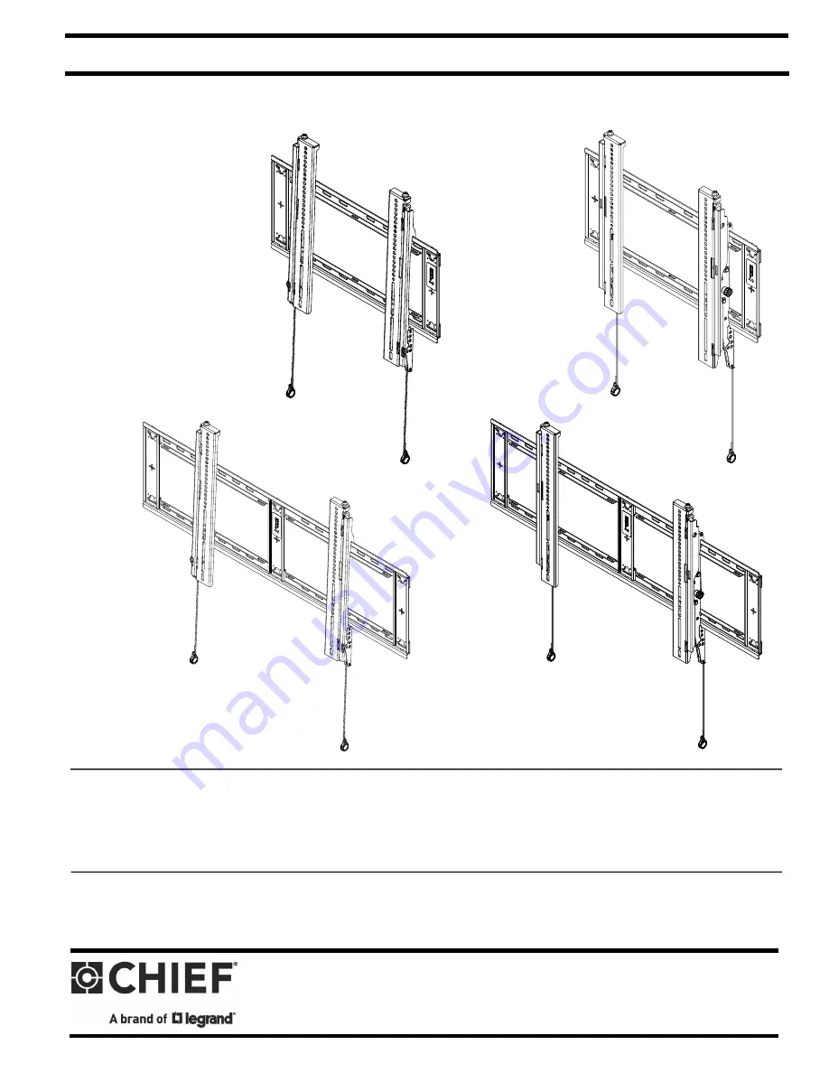
RLF3
RMT3
RLT3
FIT MEDIUM/LARGE FLAT PANEL MOUNTS
Spanish Product DescriptionGerman Product Description
RMF3/RMT3/RLF3/RLT3
Page 1: ...I N S T A L L A T I O N I N S T R U C T I O N S RMF3 RLF3 RMT3 RLT3 FIT MEDIUM LARGE FLAT PANEL MOUNTS Spanish Product Description German Product Description RMF3 RMT3 RLF3 RLT3 ...
Page 2: ...ONS WARNING Failure to read thoroughly understand and follow all instructions can result in serious personal injury damage to equipment or voiding of factory warranty It is the installer s responsibility to make sure all mounting systems are properly assembled and installed using the instructions provided WARNING Failure to provide adequate structural strength for this mounting system can result i...
Page 3: ...Installation Instructions RMF3 RMT3 RLF3 RLT3 3 DIMENSIONS DIMENSIONS INCHES MILLIMETERS RMF3 34 9 181 LEVEL ADJUST CORD LENGTH 34 9 TYP 49 13 TYP ...
Page 4: ...RMF3 RMT3 RLF3 RLT3 Installation Instructions 4 DIMENSIONS continued RMT3 DIMENSIONS INCHES MILLIMETERS 34 9 181 LEVEL ADJUST CORD LENGTH ...
Page 5: ...Installation Instructions RMF3 RMT3 RLF3 RLT3 5 DIMENSIONS continued RMT3 continued DIMENSIONS INCHES MILLIMETERS 34 9 TYP 49 13 TYP RLF3 DIMENSIONS INCHES MILLIMETERS 181 34 9 73 70 18 ...
Page 6: ... RMT3 RLF3 RLT3 Installation Instructions 6 DIMENSIONS continued RLF3 continued DIMENSIONS INCHES MILLIMETERS 34 9 TYP 49 13 TYP DIMENSIONS INCHES MILLIMETERS RLT3 51 34 9 70 18 45 CORD LENGTH LEVEL ADJUST ...
Page 7: ...Installation Instructions RMF3 RMT3 RLF3 RLT3 7 DIMENSIONS continued RLT3 continued DIMENSIONS INCHES MILLIMETERS 49 13 TYP 34 9 TYP ...
Page 8: ...üssel Chave de bocas Chiave a punte aperte Steeksleutel Clé à fourche By Hand A mano Von Hand Com a mão A mano Met de hand À la main Hex Head Wrench Llave de cabeza hexagonal Sechskantschlüssel Chave de cabeça sextavada Chiave esagonale Zeskantsleutel Clé à tête hexagonale Pencil Mark Marcar con lápiz Stiftmarkierung Marcar com lápis Segno a matita Potloodmerkteken Marquage au crayon Drill Hole Pe...
Page 9: ...y 4 G 4 M6x12mm H 4 M6x20mm Universal Hardware Kit I 4 M6x25mm K 4 J 4 M8x12mm M8x20mm L 4 M8x30mm MA 8 Nesting MB 4 Universal Wall Mounting Hardware Kit N 4 5 16 x 2 1 2 P 4 UX10x60mm Q 4 Slotted washer R 1 3 16 S 1 T 1 left right U 1 V 1 left right W 1 RLF3 RLT3 mount OR spacer Included in hardware box Included in hardware box Fixed Interface brackets washer Included in hardware box OR A 4 M4x12...
Page 10: ...tud to the left and right of the selected location RLF3 RLT3 See Figure 1 3 Line up the four slots on mount W X with the two studs previously identified See Figure 1 Figure 1 4 Using a level mark the wall on each stud to attach the mount through the upper mounting slots See Figure 2 5 Drill one 7 32 5 5mm pilot hole in each stud 6 Partially install two 5 16 x 2 1 2 flanged lag bolts N into pilot h...
Page 11: ...at no other equipment should be mounted to the same stud Figure 3 Display Mount Installation Location Must be centered on studs 16 on center studs shown RLF3 RLT3 can use 24 studs If back side of wall is unfinished drywall must be installed to a minimum of one stud left and right of the stud s being used to install the mount Drywall must be secured to studs with screws 12 on center Drywall 1 2 min...
Page 12: ...tic cap See Figure 6 9 Repeat Steps 5 through 8 for each mounting hole Figure 6 10 Place mount over anchors and align mounting holes in display mount with holes in anchors See Figure 7 11 Place 1 4 flat washer onto 1 4 20 x 1 3 4 Phillips pan head screw 12 Insert Phillips pan head screw with flat washer through mounting hole in wall mount and into anchor and tighten until flush against mount DO NO...
Page 13: ...tall two 5 16 x 2 1 2 flanged lag bolts N into upper anchors but do not tighten to wall 9 Partially install two 5 16 x 2 1 2 flanged lag bolts N into lower anchors but do not tighten to wall 10 Place one slotted washer Q over each flanged lag bolt See Figure 8 11 Tighten lag bolts to secure mount W X to wall at upper mounting slots 12 Slide mount U to approximate center of screen location Attachin...
Page 14: ... brackets S and T or U and V may be switched with the knobs on the RMT3 RLT3 interface brackets U and V facing the inside of the mount See Figure 11 Figure 11 3 If necessary the tilt interface bracket knobs may be switched to allow the interface brackets U and V to be reversed See Figure 12 a Remove display from mount b Remove interface brackets from display c Hold the right interface bracket hori...
Page 15: ... fingers hands and cables out of pinch point areas 4 Pull downward on the pull cords and swing inward toward wall latching interface brackets to lower rail and fastening bottom of screen to the mount See Figure 14 5 Attach end of pull cord a magnet to mount so it does not extend beyond bottom of screen See Figure 14 Figure 14 Adjustments Horizontal adjustment 1 The mount wall brackets may be adjus...
Page 16: ... bracket knob Figure 16 Locking Mount Optional 1 Add padlock not included to interface bracket to complete security See Figure 17 NOTE The padlock maximum shackle diameter is 5 16 7 9 mm Figure 17 Post Installation Leveling 1 If required adjust level of monitor by turning set screws on top of each interface bracket Turn screws clockwise to lower the level and counter clockwise to raise the level S...
Page 17: ...Installation Instructions RMF3 RMT3 RLF3 RLT3 17 ...
Page 18: ...RMF3 RMT3 RLF3 RLT3 Installation Instructions 18 ...
Page 19: ...RMF3 RMT3 RLF3 RLT3 Installation Instructions 19 ...
Page 20: ...480 952 225 6000 F 877 894 6918 952 894 6918 Europe A Franklinstraat 14 6003 DK Weert Netherlands P 31 0 495 580 852 F 31 0 495 580 845 Asia Pacific A Office No 918 on 9 F Shatin Galleria 18 24 Shan Mei Street Fotan Shatin Hong Kong P 852 2145 4099 F 852 2145 4477 8800 003331 Rev00 2021 Legrand AV www legrandav com 12 2021 ...