


3 109 53 Maintenance Bypass Switch
17
Installa
tion M
anual
Make sure to switch the operating modes according to the following procedures:
1. UPS MODE
UTILITY MODE (Maintenance bypass)
Step 1: Make sure the orange lamp of the MTBS is lit. If not, refer to the troubleshooting section.
Step 2: Rotate the CAM Switch (Maintenance Bypass Switch) from “UPS” position to “UTILITY”
position. At this stage the loads connected are supplied directly by the mains.
Step 3: Turn off the UPS.
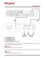
Step 4: Remove the connection between the UPS and the MTBS.
Step 5: The maintenance or replacement of the UPS may now proceed.
2. UTILITY MODE (Maintenance bypass)
UPS MODE
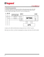
Step 1: Connect the input and output of the UPS to the MTBS, then turn on the UPS following
the instructions of its user manual.
Step 2: Make sure that the green lamp of the MTBS is lit. If not, refer to the troubleshooting section.
Step 3: Rotate the CAM Switch (Maintenance Bypass Switch) from “UTILITY” position to “UPS”
position. At this stage the loads connected are supplied by the UPS.
4 Operations
Summary of Contents for 3 109 53
Page 1: ...Part LE09522AA 08 16 01 GF 3 109 53 Maintenance Bypass Switch Installation Manual...
Page 2: ...2 ENGLISH 3 FR EN 3 109 53 Maintenance Bypass Switch...
Page 9: ...3 109 53 Maintenance Bypass Switch 9 Installation Manual 3 3 Package content 3 Installation...
Page 10: ...10 3 Installation 3 4 Rack Mount Configuration Step 1 Step 2 Step 3...


