


3 109 53 Maintenance Bypass Switch
15
Installa
tion M
anual
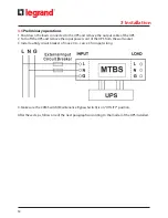
3. Connect the cable C3 to the UPS output power cord of the MTBS [1] and to the output socket
of the UPS.
4. Make sure the loads comply with the voltage and current of the UPS and the mains. If so, con-
nect the loads to the load sockets of the MTBS [5-6] using the cables C2 and C1 or those provid-
ed with the UPS. The loads are now supplied directly from the mains through the MTBS.
5. Turn on the UPS following the instructions of its user manual. When the UPS is on, the green
lamp of the MTBS [4] will light up.
6. Rotate the CAM Switch (Maintenance Bypass Switch) to “UPS” position.
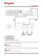
3.6.2 Procedure for Daker DK 3000 VA
C1 = cable IEC320 C19-20
C2 = cable IEC320 C15-C16
C5 = power cord Schuko - IEC320 C19
3 Installation
Summary of Contents for 3 109 53
Page 1: ...Part LE09522AA 08 16 01 GF 3 109 53 Maintenance Bypass Switch Installation Manual...
Page 2: ...2 ENGLISH 3 FR EN 3 109 53 Maintenance Bypass Switch...
Page 9: ...3 109 53 Maintenance Bypass Switch 9 Installation Manual 3 3 Package content 3 Installation...
Page 10: ...10 3 Installation 3 4 Rack Mount Configuration Step 1 Step 2 Step 3...


