14
CLASS II
INSULATED CABINETS
INSTALLATION AND FINISHES
• Internal fixings
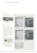
Remove the insulating screw covers
from the 4 internal fixing points on the
cabinet, then knock out the keyhole-
shaped holes. Fix the cabinet using four
Ø 6 mm screws and washers.
• External fixings
Wall-mounting lugs Cat. No. 0 201 50 can be installed in a horizontal or vertical
position.
To comply with class II it is essential to put the
insulating screw covers back in position
The keyhole-shaped openings are used to
attach and detach the cabinets
Knock out the holes corresponding to the
position of the lugs
Place the special nut and the plastic cover in
position, then screw in the lug from the back
of the cabinet
INTERNAL AND EXTERNAL FIXING CENTRES
CABINET COMBINATION
Cabinets
A (mm)
B (mm)
C (mm)
Vertical
Fixing
centre (mm)
Horizontal
Fixing centre
(mm)
4 018 02
500
305
343
107
325
4 018 03
650
455
493
107
325
4 018 04
800
605
643
107
325
4 018 05/15
950
755
763
137
325
4 018 06/16
1100
905
943
107
325
D
E
425 mm
A
B
C
625 mm
250 mm
D
E
425 mm
A
B
C
625 mm
250 mm
D
E
425 mm
A
B
C
625 mm
250 mm
D
E
425 mm
A
B
C
625 mm
250 mm
D
E
425 mm
A
B
C
625 mm
250 mm
1
FIXING THE CABINETS


