background image

www.lectrosonics.com

13

Adjusting the Input Gain

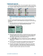
The two bicolor Modulation LEDs on the control panel provide a visual indica-

tion of the audio signal level entering the transmitter. The LEDs will glow either 

red or green to indicate modulation levels as shown in the following table.

Signal Level 

-20 LED 

-10 LED

Less than -20 dB 

 Off 

 Off

-20 dB to -10 dB  

 Green 

 Off

-10 dB to +0 dB 

 Green  

 Green

+0 dB to +10 dB 

 Red 

 Green

Greater than +10 dB 

 Red 

 Red

NOTE:  Full modulation is achieved at 0 dB, when the “-20” LED first 

turns red. The limiter can cleanly handle peaks up to 30 dB above this 

point.

It is best to go through the following procedure with the transmitter in the 

standby mode so that no audio will enter the sound system or recorder during 

adjustment.

1)  With fresh batteries in the transmitter, power the unit on in the standby 

mode (see previous section 

Turning Power ON and OFF

).

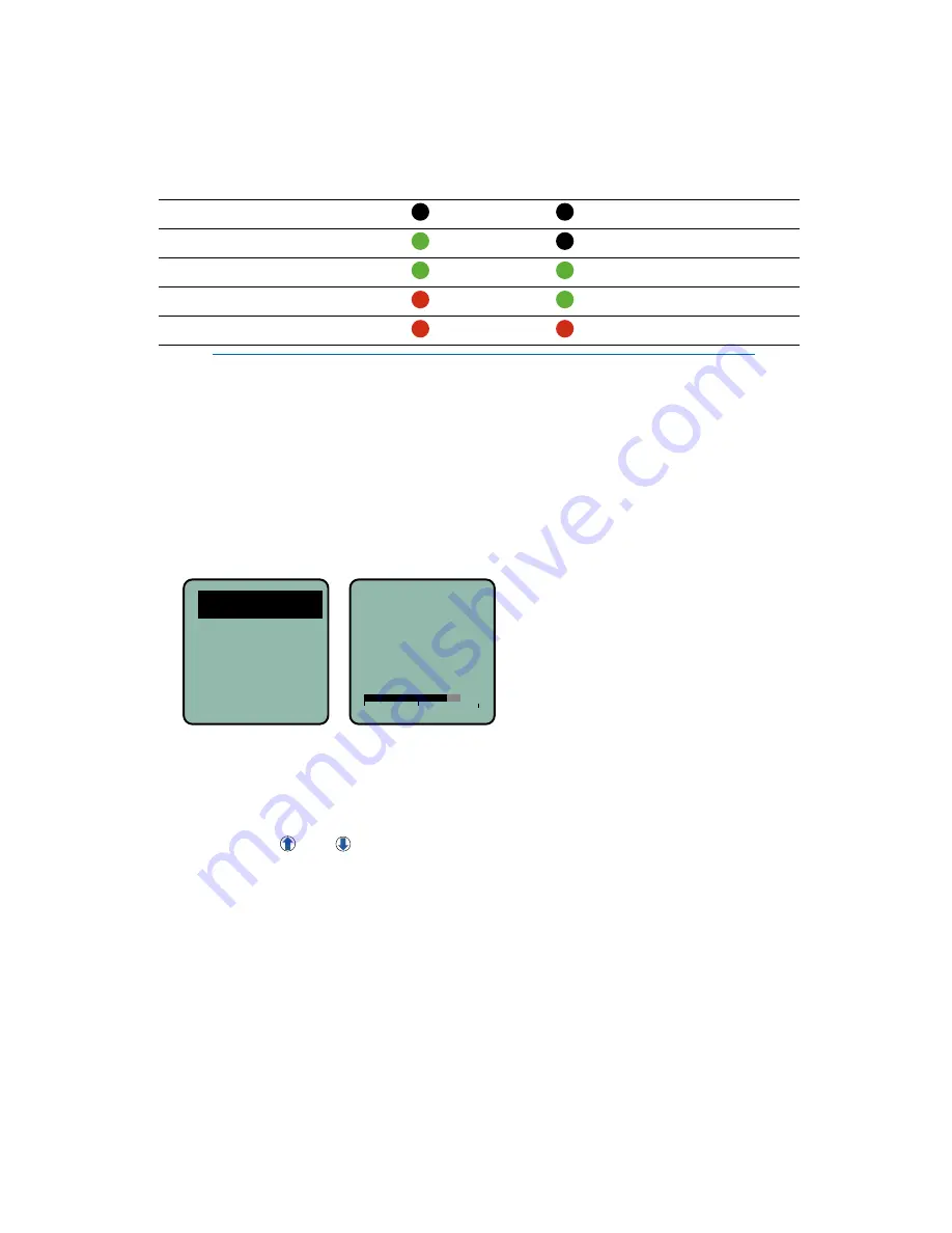
2)  Navigate to the Gain setup screen.

Gain

Freq
Rolloff
Compat

-40

-20

0

Gain

25

3)  Prepare the signal source. Position a microphone the way it will be used 

in actual operation and have the user speak or sing at the loudest level 

that will occur during use, or set the output level of the instrument or 

audio device to the maximum level that will be used.

4)  Use the   and   arrow buttons to adjust the gain until the –10 dB glows 

green and the 

–20 dB LED starts to flicker red during the loudest peaks 

in the audio.

5)  Once the audio gain has been set, the signal can be sent through the 

sound system for overall level adjustments, monitor settings, etc. 

6)  If the audio output level of the receiver is too high or low, use only the 

controls on the receiver to make adjustments. Always leave the trans-

mitter gain adjustment set according to these instructions, and do not 

change it to adjust the audio output level of the receiver.

Summary of Contents for SMWB series

Page 1: ...his guide is intended to assist with initial setup and operation of your Lectrosonics product For a detailed user manual down load the most current version at www lectrosonics com SMWB Series Transmitters 05 April 2018 Digital Hybrid Wireless US Patent 7 225 135 SMWB SMDWB ...

Page 2: ... transmitter to also be used with a variety of analog receivers by emulating the compandors found in earlier Lectrosonics analog wireless and IFB receivers and certain receivers from other manufactur ers contact the factory for details Plus the SMWB has a built in recording function for use in situations where RF may not be possible or to work as a stand alone recorder The record function and tran...

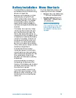
Page 3: ...t to leave any remnants of the cotton swab or eraser crumbs inside the compartment A small pinpoint dab of silver conductive grease on the thumb screw threads can improve battery performance and operation Do this if you experience a drop in bat tery life or an increase in operating temperature Insert the batteries according to the markings on the back of the housing If the batteries are inserted i...

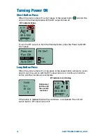
Page 4: ...r button Rf On option Resume Pwr Off Rf On AutoOn Rf On No Yes Long Button Press When the unit is turned off a long press of the power button will start a count down to turn the unit on with the RF output turned on Continue to hold the button until the countdown is complete Hold for Rf On 3 A 503 800 40 20 0 E b 19 RF indicator not blinking Hold power button until the counter reaches 3 If the butt...

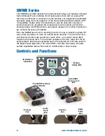
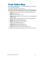
Page 5: ...reen and operating mode Pwr Off turns the unit off Rf On turns the RF output on or off AutoOn selects whether or not the unti will turn on automatically after a battery change Remote enables or disables the audio remote control dweedle tones Bat Type selects the type of battery in use Backlit sets the duration of the LCD backlight Clock sets the Year Month Day Time Locked disables the control pane...

Page 6: ...e gain until the 20 LED blinks red on louder peaks Signal Level 20 LED 10 LED Less than 20 dB Off Off 20 dB to 10 dB Green Off 10 dB to 0 dB Green Green 0 dB to 10 dB Red Green Greater than 10 dB Red Red Set the frequency and compatibility mode to match the receiver Turn the RF output on with the Rf On item in the power menu or by turning the power off and then back on while holding the power butt...

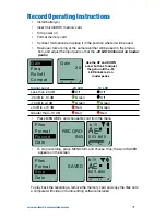
Page 7: ... arrow buttons to adjust the gain until the 20 LED blinks red on louder peaks Signal Level 20 LED 10 LED Less than 20 dB Off Off 20 dB to 10 dB Green Off 10 dB to 0 dB Green Green 0 dB to 10 dB Red Green Greater than 10 dB Red Red Press MENU SEL and choose Record from the menu A 503 800 40 20 0 E b 19 REC Files Format Record Gain RECORD ING To stop recording press MENU SEL and choose Stop the word...

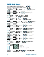
Page 8: ...n Select from listing b 21 80 550 400 Hybrid From the Main Window press MENU SEL Use the UP Down arrow keys to select the item Files SEL BACK Files 0014A000 0013A000 Use arrow keys to select file in list Select from listing Format SEL BACK Use arrow keys to initiate formatting the memory card No Yes Format erases Gain SEL BACK Gain 22 Use arrow keys to select input gain Select from listing Record ...

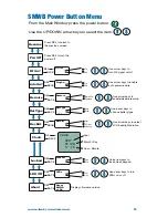
Page 9: ...the power button Use the UP DOWN arrow keys to select the item Resume Pwr Off Press SEL to turn the power off AutoOn SEL BACK ProgSw Use arrow keys to enable auto power restore No Yes 1 5 V Backlit SEL BACK Backlit Use arrow keys to select LCD backlight duration On 30 sec 5 min About Locked SEL BACK About SMWB v1 00 Displays firmware version SEL BACK Use arrow keys to lock unlock keypad Yes No Loc...

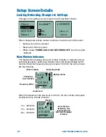
Page 10: ...ow Indicators The Main Window displays the band number Standby or Operating mode operating frequency audio level battery status and programmable switch function When the frequency step size is set at 100 kHz the LCD will look like the following 474 500 40 20 0 b 470 2C Block number Frequency MHz Frequency hex number Operating mode Battery status Audio level When the frequency step size is set to 2...

Page 11: ...h the proper wiring Refer to the section on Input Jack Wiring for Different Sources for details Turning Control Panel LEDs ON OFF From the main menu screen a quick press of the UP arrow button turns the control panel LEDs on A quick press of the DOWN arrow button turns them off The buttons will be disabled if the LOCKED option is selected in the Power Button menu The control panel LEDs can also be...

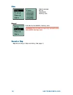
Page 12: ... 0006A000 Files Format Record Gain Select recorded files on microSDHC memory card Format Files Format Record Gain Formats the microSDHC memory card WARNING This function erases any content on the microSDHC memory card Record or Stop Begins recording or stops recording See page 7 ...

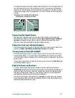
Page 13: ...r the unit on in the standby mode see previous section Turning Power ON and OFF 2 Navigate to the Gain setup screen Gain Freq Rolloff Compat 40 20 0 Gain 25 3 Prepare the signal source Position a microphone the way it will be used in actual operation and have the user speak or sing at the loudest level that will occur during use or set the output level of the instrument or audio device to the maxi...

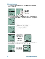
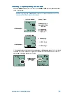
Page 14: ... in the 25 kHz mode from the 100 kHz mode Freq b 19 494 500 51 Freq b 19 494 500 51 These two fields step in 25 kHz increments when the step size is 25 kHz and 100 kHz increments when the step size is 100 kHz Freq b 19 494 500 51 Freq b 19 494 500 51 These two fields always step in the same increments 1 MHz steps 1 block steps A fraction will appear next to the hex code in the setup screen and in ...

Page 15: ...51 1 block steps 1 6 MHz steps to nearest 100 kHz channel 10 MHz steps 100 kHz steps to next 100 kHz channel 100 kHz Mode Freq b 19 494 525 511 4 1 block steps 1 6 MHz steps 10 MHz steps 25 kHz steps 25 kHz Mode If the Step Size is 25 kHz with the frequency set between even 100 kHz steps and the Step Size is then changed to 100 kHz the mismatch will cause the hex code to display as two asterisks 4...

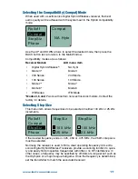
Page 16: ...t one is in band 470 and the other in band 19 This is done intentionally to maintain compatibility with receivers that tune across a single band The band number and hex code must match the receiver to enable the correct pilot tone Freq b470 494 500 F4 Freq b 19 494 500 51 Make sure the band number and hex code match the receiver setting Selecting the Low Frequency Roll off Low frequency audio cont...

Page 17: ...nd 7 work with certain non Lectrosonics models Contact the factory for details Selecting Step Size This menu item allows frequencies to be selected in either 100 kHz or 25 kHz increments Rolloff Compat StepSiz Phase StepSiz 100 kHz 25 kHz StepSiz 100 kHz 25 kHz If the desired frequency ends in 025 050 or 075 MHz the 25 kHz step size must be selected Normally the receiver is used to find a clear op...

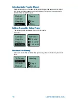
Page 18: ...arity can also be in verted at the receiver outputs Rolloff Compat StepSiz Phase Phase Pos Neg Setting Transmitter Output Power The output power can be set to 25 mW 50 mW or 100 mW Compat StepSiz Phase TxPower TxPower 25 mW 50 mW 100 mW Recorded File Naming Choose to name the recorded files by the sequence number or by the clock time Naming Seq Clock TxPower Naming SD Info Default ...

Page 19: ...including space remaining on card TxPower Naming SD Info Default SMWB Max Rec E F 0 14G Fuel gauge Storage used Storage capacity Available recording time H M S Restoring Default Settings This is used to restore the factory settings TxPower Naming SD Info Default Default settings No Yes ...

Page 20: ......

Reviews: