


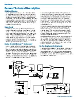


Super-Minature Belt Pack Transmitters
Operating Instructions
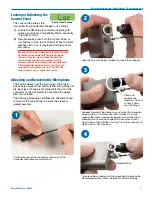
Power Up and Boot Sequence
1)
Ensure that good batteries are installed in the unit.
(See
Battery Installation
.)
2)
Simultaneously press and hold the AUDIO and
FREQ buttons until the Power On Boot Sequence is
initiated. (See Power On Timer.) As the unit turns
on, the Modulation LEDs and PWR LED all glow red,
then green, and then they revert to normal opera
tion, i.e., the Modulation LEDs glow according to the
audio level present at the Audio Input Jack and the
PWR LED glows green (with good batteries).
Modulation
LEDs
AUDIO
Button
PWR LED
FREQ
Button
UP Arrow
DOWN Arrow
The LCD displays a bootup sequence which con
sists of four screens:
Company Name:
Lectro
Frequency Block (bXX) and
Firmware Version (rX.X):
b21r1.1 (typ)
Compatibility Mode:
CP 400 (typ)
Audio:
Aud 12 (typ)
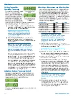
Power Down
1)
Simultaneously press
and hold the AUDIO
Initial Power Off
and FREQ buttons while
Timer Screen
observing that the word
“Off” appears in the LCD along with a counter.
2)
When the counter reaches “0”, the unit turns off.
Note: If the AUDIO and FREQ buttons are
released before the LCD goes blank at the end of
the countdown, the unit will not turn off. Instead, it
will stay energized and the display will return to the
previous screen.
Standby Mode
Standby Mode allows the user to verify or change the
transmitter’s operating frequency or audio input level
without transmitting any signals. Standby Mode can
only be invoked from a power off condition.
Quickly press and release both the AUDIO and FREQ
buttons simultaneously to enter and exit this mode.
Selecting the
Compatibility Mode
400 Series or Digital
All Digital Hybrid Wireless™
Hybrid Wireless™
receivers are capable of work-
compatibility mode
ing with the Lectrosonics SM
transmitter. By selecting the proper compatibility mode,
the SM will also work with 200 Series, 100 Series and
IFB analog receivers, plus some other analog wire
less receivers (contact the factory for details). Setting
the Compatibility Mode of the transmitter to match the
receiver is easily done via the Control Panel.
Note: RF transmission is prevented while selecting
Compatibility Modes. Also, the SM exits the
Compatibility Mode screen to Standby Mode. (See
Standby Mode, this section.)
Note: The unit comes from the factory configured
as a 400 Series transmitter.
1)
Set the receiver’s audio controls to minimum.
2)
Power up the SM and observe the Boot Sequence.
If the Compatibility Mode for the SM does not match
the corresponding receiver, then power off the SM
transmitter.
3)
From a power off condition, hold down the Up
arrow, then simultaneously press the AUDIO and
FREQ buttons.
4)
The LCD will display the current Compatibility
Mode. Use the Up or Down arrow buttons to set
the Compatibility Mode to match the corresponding
receiver.
The following Compatibility Modes are available:
•
100
Series
mode:
CP
100
•
200
Series
mode:
CP
200
•
Mode
3
(Contact
dealer
for
details):
CP
3
•
400
Series
mode:
CP
400
•
IFB
Series
mode:
CP
IFB
•
Mode
6
(Contact
dealer
for
details):
CP
6
5)
The Compatibility Mode selected in Step 4 will be
the current Compatibility Mode until reset using this
procedure. Pressing the AUDIO or FREQ exits into
Standby Mode. To power off from the compatibility
mode screen, press AUDIO and FREQ together.
Rio Rancho, NM
9