Lectrosonics SMa Series Instruction Manual Download Page 17

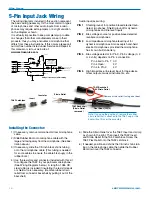
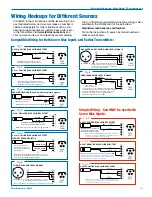
Super-Minature Belt Pack Transmitters 

Operating Notes 


The


sensitivity


to


the


remote


control varies with the trans­

mitter’s audio level setting 

and the microphone used, but 

it is always possible to make 

it work with a sufficiently loud 

remote signal at close range. 

• 


If


the


SMa


is


configured


to


respond to the remote con­

trol, it will do so even if the 

buttons are locked. 

• 


When


the


SMa


is


asleep,


it


can only be awakened by the 

remote control, or by remov­

ing and reinserting the bat­

tery. 

• 


When


the


SM


is


asleep,


the


PWR led blinks green every 

few seconds. 

• 


If


a


remote


command


is


sent


that


would


result


in


the same display being shown again on the SM (for 

example tuning to the channel already displayed), 

a row of dashes is displayed briefly, as a signal that 

the command was received, but it didn’t change 

anything. 

• 


If


you


are


having


trouble


getting


the


SMa


to


re

­

spond, make sure you aren’t covering the RM’s 

speaker with your thumb, and/or turn up the RM’s 

speaker volume on the “Loud” page. 

• 


If


the


RM


is


set


to


a


different


block


number


than


the transmitter and an attempt is made to set the 

transmitter’s frequency in MHz, the command 

will still work. The transmitter is simply set to the 

corresponding channel in the correct block, with a 

matching hex code. 

• 


Since


all


SM


transmitters


respond


to


the


same


sig

­

nals, take care that the remote control is presented 

only to the desired transmitter, with the minimum 

speaker volume necessary to do the job reliably. 

Note:  The audio signal from the RM will change 

the settings of all transmitters within range. 

Experiment with this to prevent accidental changes 

to another transmitter during a production. 

The RM should be held close enough to the microphone to 

change the settings on the intended transmitter, but not be so 

loud as to affect other transmitters nearby. 
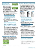
RM Quick Reference 

Power On/Off 

AUDIO+FREQ 

Set SM audio level 

Aud page (via AUDIO) 

Sleep or Wake SM 

SLEEP/unSLP page (via AUDIO) 

Lock or Unlock SM 

Loc/unLoc page (via AUDIO) 

Adjust RM volume 

Loud page (via AUDIO) 

Set SM channel (hex) 

CH page (via FREQ) 

Enable MHz display 

b (block) page (via FREQ) 

Set SM channel (MHz) 

000.000 page (via FREQ) 

Important:  The remote control (RC) mode must 

be enabled on your SM Series transmitter for 

the RM to function with it.  For instructions, 

refer to page 8 of this publication. 

Rio Rancho, NM 

17


Summary of Contents for SMa Series

Page 1: ...e Belt Pack Transmitters With Digital Hybrid Wireless Technology SMa Single battery 100 mW RM Remote Control Digital Hybrid Wireless US Patent 7 225 135 Fill in for your records Serial Number Purchase...

Page 2: ...SMa Series LECTROSONICS INC 2...

Page 3: ...d perspiration in extreme envi ronments Table of Contents General Technical Description 4 Controls and Functions 6 LCD Screen 6 Power LED 6 Audio Input Jack 6 Battery Compartment and Thumb Screw 6 Mod...

Page 4: ...defeat the noise by sending the audio information in digital form at the cost of some combination of power bandwidth and resistance to interference US Patent 7 225 135 Lectrosonics Digital Hybrid Wire...

Page 5: ...correct pilot tone is added to the encoded signal Compatibility Modes The SM transmitters were designed to operate with Lectrosonics Digital Hybrid receivers and will yield the best performance when d...

Page 6: ...or secure the Battery Compartment Cover Plate allowing access to the battery Modulation LEDs The Modulation LEDs provide a visual indication of the input audio signal level from the microphone These t...

Page 7: ...ing and holding the AUDIO and FREQ buttons displays a timer with numerals on the right The numerals count up from one and the boot sequence begins when the count reaches three LECtro is displayed as t...

Page 8: ...ailable from the remote control are Audio Level Frequency Lock Unlock Buttons Sleep Wake power saving mode In sleep mode the SM uses 20 of the normal amount of current For example in sleep mode it wil...

Page 9: ...imultaneously to enter and exit this mode Selecting the Compatibility Mode 400 Series or Digital All Digital Hybrid Wireless Hybrid Wireless receivers are capable of work compatibility mode ing with t...

Page 10: ...n The control panel Modulation LEDs indicate the modu lation level and limiter activity Once set the transmit ter s audio level setting should not be used to control the volume of your sound system or...

Page 11: ...cked mode Attaching and Removing the Microphone The flexible sleeve over the 5 pin plug on the micro phone helps prevent dust and moisture from getting into the input jack A flange is machined into th...

Page 12: ...o Limiter Control LINE IN PIN 5 High impedance line level input for tape decks 3 3uF mixer outputs musical instruments etc SM Equivalent Input Circuit Wiring 10k 2 7K TA5F Latchlock Insert Insulator S...

Page 13: ...lamp the insulation Strip and position the cable so that the clamp can be crimped to contact both the mic cable shield and the insulation The shield contact reduces noise with some microphones and the...

Page 14: ...ling RF bypass capacitors at the mic capsule If this is not pos sible or if you are still having problems capacitors can be installed on the mic pins inside the TA5F connector housing 2 WIRE MIC 3 WIR...

Page 15: ...e inserted in series with Pin 5 for an additional 20 dB of attenuation to handle up to 30V 32 dBu Fig 8 1 2 3 4 5 PIN SHIELD AUDIO 1 2 3 4 5 TA5F PLUG 2 7 k 2 VOLT NEGATIVE BIAS 2 WIRE ELECTRET Compat...

Page 16: ...interface is organized into pages which are accessible via the AUDIO and FREQ buttons Once on a page settings can be adjusted with the UP and DOWN arrow buttons To change a transmitter s setting via...

Page 17: ...attempt is made to set the transmitter s frequency in MHz the command will still work The transmitter is simply set to the corresponding channel in the correct block with a matching hex code Since al...

Page 18: ...ches display on transmitter and receiver 5 Transmitter and receiver not on same frequency block 6 Operating range is too great 7 Defective transmitter antenna unit needs repair NO SOUND OR LOW SOUND L...

Page 19: ...en the unlocked condition was indicated TRANSMITTER WON T RESPOND TO REMOTE CONTROL 1 If LCD blinks rc oFF transmitter has not be configured to respond to the remote control See Remote Control Operati...

Page 20: ...k of unit as pictured SMBCUPSL Spring loaded machined aluminum clip Antenna and mic connector will face up 35923 Thermal insulated pad installed on SMa PSM Leather pouch with integrated belt clip Plac...

Page 21: ...RF exposure using this product This device complies with FCC radiation exposure limits as set forth for an uncontrolled environment This device should be installed and operated so that its antenna s...

Page 22: ...for Repair For timely service please follow the steps below A DO NOT return equipment to the factory for repair without first contacting us by email or by phone We need to know the nature of the probl...

Page 23: ...Super Minature Belt Pack Transmitters Rio Rancho NM 23...

Page 24: ...aler shipping costs prepaid within one year from the date of purchase This Limited Warranty is governed by the laws of the State of New Mexico It states the entire liablility of Lectrosonics Inc and t...

Reviews: