


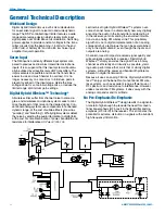
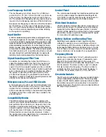


Super-Minature Belt Pack Transmitters
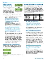
Locking or Unlocking the
Control Panel
Control Panel Locked
The Lock mode protects the
transmitter from accidental changes to its settings.
1)
Ensure the SM setup is complete (operating fre
quency, audio level, Compatibility Mode, sensitivity
to remote control).
2)
Simultaneously press both the Up and Down ar
row buttons to start the Lock timer. When the timer
reaches zero, “Loc” is displayed and the controls
are locked.
Important: Once the transmitter is locked, it cannot
be unlocked or powered off using the buttons.
The only ways to unlock a locked transmitter
are to remove the battery or unlock it via the
remote control. The remote control will work only
2
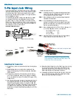
Align the pins on the plug and jack and insert the connector.
if the transmitter was previously configured to
respond to the remote control. The unit will
always power up in “unlocked” mode.
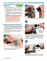
Attaching and Removing the Microphone
The flexible sleeve over the 5-pin plug on the micro
phone helps prevent dust and moisture from getting into
the input jack. A flange is machined into the rim of the
connector on the transmitter to help retain the sleeve
after it is installed.
The following procedure simplifies the attachment and
removal of the microphone to assure the sleeve is
seated securely.
3
Pinch and
squeeze the
sleeve on this end
to work it down
over the flange.
Squeeze the end of the sleeve so you can feel the connector
inside and press it into the jack until it latches. Pinch and
squeeze the sleeve near the flange and work it down with a
kneading motion over the flange all the way around until it
stays in place flush with the housing. Pull on the connector to
make sure it is firmly latched.
1
Pull the sleeve over the connector so the ends of the
connector and sleeve are almost flush.
4
Release button
To remove the connector, pull the sleeve back to expose the
black release button. Press the button to unlatch the plug.
Rio Rancho, NM
11