background image

Leaf LT88 / LT88E manual 


Page  17  Of  22 


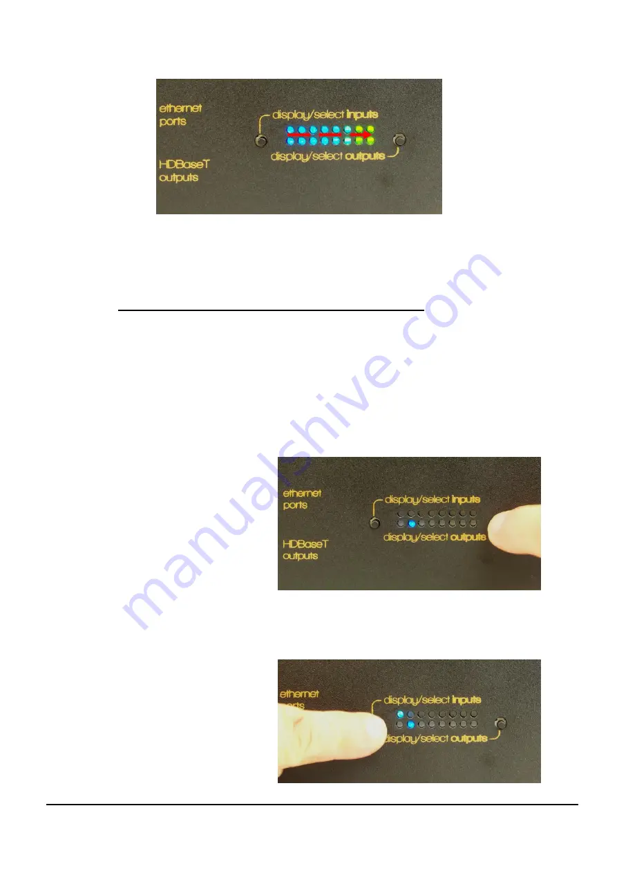
The calibration process may take up to a minute or two and when finished, the 
LEDs will display  (green)  any  previously selected sources and zones or  revert 
to standby (top left LED only, pulsing green/blue) if that was the previous state. 
 

6.3  Creating input to output switched selections 

While this would typically be performed by RS232 commands from your control system, 
basic selections may also be performed manually by following these steps in 
sequence.  


Manually select output zone  

Press the right hand press button switch sequentially until the LED in the lower row 
corresponding to the desired output (zone) is blue, then release the switch and proceed 
to the next step. 

The lower row of LEDs indicates the output zones 1 to 8 left to right. 


(Zone 2 is depicted in this picture) 


Manually select the input source for that Zone 

Press the left hand press button switch sequentially until the LED in the upper row 
corresponding to the desired input (source) is blue, then release the switch. 
The upper row of LEDs indicates the input sources 1 to 8 left to right. 
 
(Source 1 is depicted in this picture) 


Summary of Contents for Leaf True LT88

Page 1: ...8 X 8 Video Matrix Systems LT88 LT88E...

Page 2: ...tion please switch off and unplug mains power from this system and any equipment that is to be connected to it prior to connecting any leads cables Plug in and switch power back on again after all int...

Page 3: ...1 Single LT88 E use 10 3 8 2 Multiple LT88 E use 10 3 9 Bank Select Switch 11 3 10 RS232 Termination TERM Switch 11 3 11 HDMI Input ports 11 4 BREAKOUTS 12 4 1 Local Power 12 4 2 Mounting Bracket 12...

Page 4: ...ures the LT88E extends this by providing Ethernet through feed capability The LT88E has additional circuitry and dedicated RJ45 type ports on its front panel that connect to matching Ethernet ports at...

Page 5: ...e metal housings and are provided with rubber feet should table desktop mounting be preferred 2 Front Panel Layout The LT88 and LT88E front panels are fitted with connectors visual indicators and cont...

Page 6: ...Ethernet ports indicate handshake between the LT88E and host Ethernet devices to which it is connected but does not necessarily indicate data flow from end to end 2 3 Front Panel LED display and selec...

Page 7: ...ype Leaf Control input port 2 1 x 4 way Dip Switch module 3 8 x RCA S PDIF digital coax audio input sockets 4 8 x pairs of RCA line level stereo output sockets 5 8 x 3 5mm Tip Ring Sleeve sockets for...

Page 8: ...N with a stereo tip ring sleeve plug at the Leaf end with the ring floating not connected or with the ring connected to tip 3 Normal Mode Compatibility Mode 4 Future Function Future Function Table 1 D...

Page 9: ...r similar instead of stand alone IR detectors For this configuration Stereo Tip Ring Sleeve 3 5mm leads must be used instead of Mono leads for the IR interconnections from the control system to the Le...

Page 10: ...th a straight through DB9 Male to Female RS232 lead Some control systems may require only the TxD RxD and Gnd wires of an RS232 lead to be connected The pin configurations of these 3 connections on th...

Page 11: ...8h to 3Fh 8 65 to 72 64 to 71 40h to 47h 9 73 to 80 72 to 79 48h to 4Fh A 81 to 88 80 to 87 50h to 57h B 89 to 96 88 to 95 58h to 5Fh C 97 to 104 96 to 103 60h to67h D 105 to 112 104 to 111 68h to 6Fh...

Page 12: ...45 type socket for Ethernet throughput and is designed to match the capabilities of the LT88E 4 1 Local Power Each breakout LTB1 LTB1E is required to be powered by its own local power supply and to be...

Page 13: ...active LED 2 ON The HDBaseT Cat5e Cat6 cable link to the LT88 E has been made successfully and is ready for video LED 3 ON Protected HDCP video content is being transferred on the HDBaseT link FLASHIN...

Page 14: ...ive Source Selection Zone Lock mode A source can be locked to a particular zone The exclusive source selection feature enables enhanced features such as multichannel audio 3D etc to become active in t...

Page 15: ...t connectors on the LT88 LT88E The source range for the selected audio inputs under this feature becomes HDMI input ports 1 to 8 LTB1 LTB1E Breakouts 9 to 16 LT88 LT88E 17 to 24 This feature is activa...

Page 16: ...dicated by the upper left hand LED only pulsing green blue 6 2 Calibration The system should be calibrated on first use or after any new devices source or zone equipment are added or port allocations...

Page 17: ...ng these steps in sequence Manually select output zone Press the right hand press button switch sequentially until the LED in the lower row corresponding to the desired output zone is blue then releas...

Page 18: ...second step above the left hand press button switch is pressed until no Blue LEDs are displayed in the upper row the connection will be cleared i e the output will be disconnected from the input 6 4...

Page 19: ...f LT88 LT88E manual Page 19 Of 22 7 Interconnections 7 1 Possible interconnections at front panel LT88E depicted LT88 is similar but without the Ethernet ports 7 2 Possible interconnections at rear pa...

Page 20: ...Leaf LT88 LT88E manual Page 20 Of 22 7 3 Possible interconnections at LTB1E LTB1 is similar but without the Ethernet port...

Page 21: ...rol 1x RS232 DB9 IN 1x RS232 DB9 LOOPOUT Bank select and termination selectors 6 INFRA RED REMOTE CONTROL THROUGHPUT ONLY No direct control by IR 8x DIRECTIONAL IR INPUTs Support for Direct IR IR TX B...

Page 22: ...ncrease the separation between the equipment and receiver Connect the equipment into an outlet on a circuit different from that to which the receiver is connected Consult the dealer or an experienced...

Reviews: