High Voltage Digital Stepper Drive DM2282 Manual
Page 4 of 7
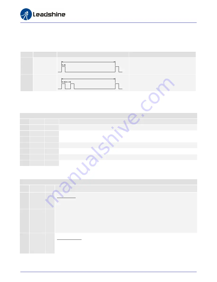
Protection Indications
The green indicator turns on when power-up. When drive protection is activated, the red LED blinks periodicity to indicate the error type
Priority
Time(s) of Blink
Sequence wave of RED LED
Description
1st
1
0.2S
3S
Over-current Protection
2nd
2
0.2S
0.3S
3S
Over-voltage Protection
Pin Assignment
The DM2282 has one barrier strip connector for power and motor connections and one screw terminal for control signal connections.
Power and Motor Connector
Pin
Name I/O
Description
1
PE
-
Recommend connect this port to the ground for better safety.
2
L
I
Power supply inputs. If AC input, recommend use isolation transformers with
theoretical output voltage of 150~230VAC.
3
N
I
4
A+
O
Motor Phase A+
5
A-
O
Motor Phase A-
6
B+
O
Motor Phase B+
7
B-
O
Motor Phase B-
Pin Assignment
Control Signal Connector
Pin
Name I/O Description
1
PUL+
I
Pulse Signal: In single pulse (pulse/direction) mode, this input represents pulse signal, each
rising or falling edge active (software configurable, see DM drives software operational
manual for the detail); In double pulse mode (software configurable), this input represents
clockwise (CW) pulse, active both at high level and low level. 4-5V when PUL-HIGH,
0-0.5V when PUL-LOW. For reliable response, pulse width should be longer than 2.5μs.
Series connect resistors for current-limiting when +12V or +24V used. The same as DIR and
ENA signal.
2
PUL-
I
3
DIR+
I
Direction Signal: In single-pulse mode, this signal has low/high voltage levels, representing
two directions of motor rotation. In double-pulse mode (software configurable), this signal is
counter-clock (CCW) pulse, active both at high level and low level. For reliable motion


