CS-D808 Closed Loop Stepper Drive User Manual
Page | 3
3. Connections and LED Indication
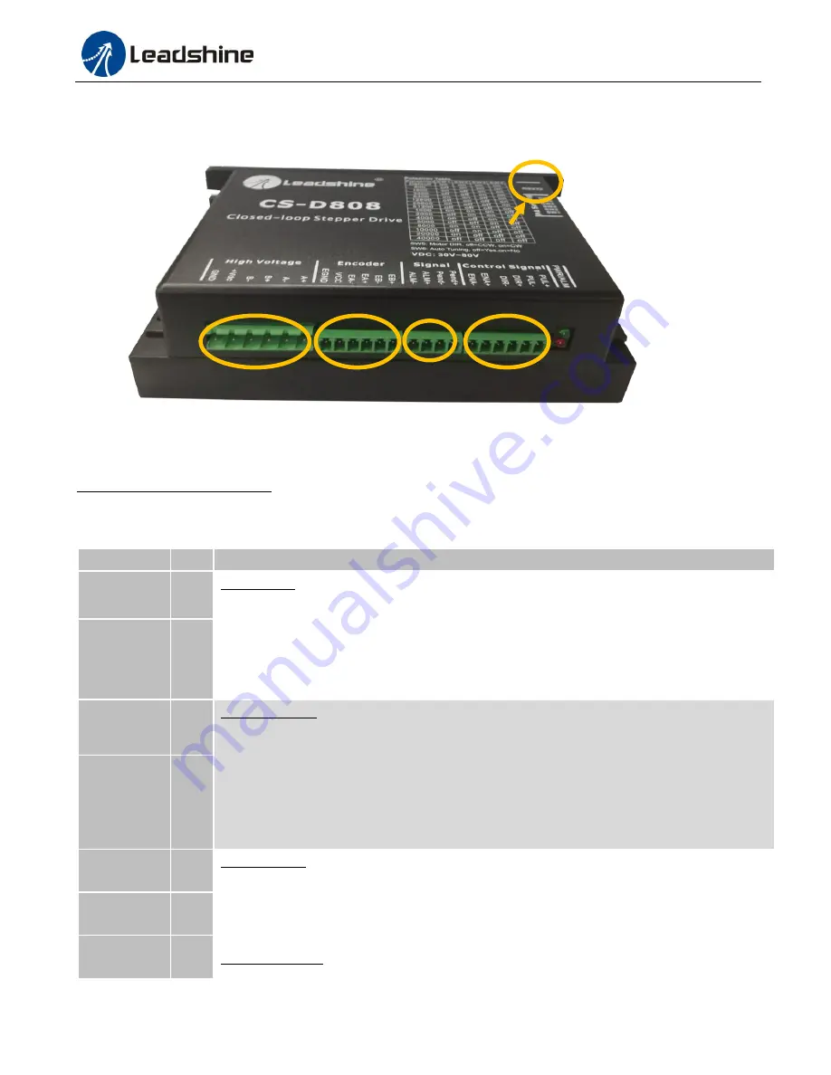
A CS-D808 closed loop stepper drive has 5 connection blocks from P1 to P5 (see figure 2).
Figure 2: CS-D808 connectors
3.1 Connector P1 & P2– Control Input and Output Connections
3.1.1 Pin Assignments of P1 & P2
The P1 & P2 connector in Figure 2 is for control signal and fault output connections. Refer to the following table for
details.
Pin Name
I/O
Details
PUL+
I
Pulse signal:
(1)
. In single pulse (pulse & direction) control mode, this input represents pulse
signal. A pulse signal is active at the rising or falling voltage edge (set by PC software).
(2).
In
double-pulse (CW/CCW) control mode (set by PC software), this signal input represents
clockwise (CW) pulse, and is active at both high voltage level and low voltage level.
(3).
4.5-24V for voltage HIGH, 0-0.5V for voltage LOW (same for DIR and ENA signals).
(4).
Pulse width should be set to 2.5μs or longer.
PUL-
I
DIR+
I
Direction signal:
(1).
In single pulse (step & direction) control mode, this signal’s low and high
voltage levels represent the two directions of motor rotation (e.g. clockwise and
counterclockwise).
(2).
In double-pulse (CW & CCW) control mode, this signal represents
counterclockwise (CCW) rotation. It is active at both voltage high level and low level.
(3).
Minimal DIR signal setup time should be at least 5μs.
(4).
Rotation direction is related to your
motor/drive wiring. You can reverse the default rotation direction by toggling the SW5 DIP
switch.
DIR-
I
ENA+
I
Enable signal: This signal is used for enabling/disabling the drive. High voltage level of
4.5-24V (NPN control signal) for enabling the drive and low voltage level of 0-0.5VDC for
disabling the drive. PNP and Differential control signals are on the contrary, namely Low level
for enabling. By default this signal is left
UNCONNECTED & ENABLED
.
ENA-
I
Pend+
O
In-position Signal: OC output signal, active when the difference between the actual position and
P1
P2
P3
P4
P5


