Tel: +44 (0)1981 241668
Skyrrid Farm, Pontrilas, Hereford. HR2 0BW. UK
www.leturbines.com
Page 26 of 28
Ensure that you have followed the cable-sizing guidelines to ensure that the correct size of cable
has been selected. If a cable of insufficient cross-sectional area is used at any point in the electrical
system, heat will build up in the cables causing a potential fire hazard. A properly-sized fuse or
circuit breaker should be used in the cables connected to the battery. This will stop the risk of short
circuit currents.
Batteries used in renewable energy systems can deliver a serious amount of current. A short circuit
in the battery circuit can lead to hundreds of Amps flowing through the battery cables. This will
cause a heat build-up and ultimately an electrical fire. Batteries are also susceptible to exploding
when shorted. Always use insulated electrical tools when working on the battery’s electrical
connections.
Batteries are very heavy. Do not attempt to move batteries by yourself. Always use manual
handling tools and an assistant. Always keep lead-acid batteries the correct way up. Do not allow
the acidic electrolyte to spill or come into contact with your skin or face. Always follow the
manufacturer’s safety instructions when handling lead-acid batteries. Ensure that the Universal Run
/ Stop switch is correctly wired as per these instructions and wiring schematics. Incorrect wiring
may lead to a short circuit being placed across the batteries which can lead to fire or explosion.
Please use common sense when installing and operating your turbine and associated equipment.
Installation
Please refer to electrical schematic for appropriate generic wiring diagrams.
The Universal Run / Stop Switch can either be mounted in the enclosure box (supplied), which in
turn can be mounted on an internal panel, or the switch can be integrated into an existing panel.
If the unit is to be integrated into an existing panel, a suitable cut-out, as detailed on the wiring
diagram will need to be made.
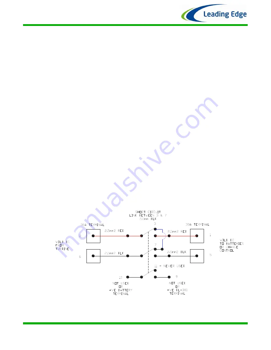
Switch Wiring – please ensure all 12 screw terminals of the switch are screwed closed before
finally placing the top cover on the switch:


