


Tel: +44 (0)1981 241668
Skyrrid Farm, Pontrilas, Hereford. HR2 0BW. UK
www.leturbines.com
Page 11 of 28
‘Earth’ the System - The turbine tower should have its own separate earth point. The
negative terminal of the battery bank should also be earthed. This provides protection
against the build-up of static and lightning strikes. The tower should be earthed separately
with its own ground rod if there is a long transmission distance between the tower and
batteries. An appropriate surge arrestor could also be used to help prevent damage to the
battery charging system during a lightning strike. Ensure that the earth cables are of the
same rating as the positive and negative cables.
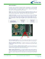
Cable Selection - The cable size table should be used to select the minimum sized cable for
a given transmission distance. Voltage drop in the cable will be improved if a larger cable is
used.
Fuses - The turbine and charging circuit should be protected with a suitably rated ‘slow-
blow’ DC fuse or DC circuit breaker. Please refer to the table below for the correct rating.
The fuse or breaker should be positioned between the turbine and batteries (on the
positive cable). If a stop switch is used (recommended) the fuse should be positioned
between the switch and the batteries.
Run / Stop Switch - A simple switch arrangement can provide a safe and easy way of
stopping the turbine for maintenance. Leading Edge Turbines can supply a switch which is
best for this purpose. As the switch is thrown, the batteries are disconnected and the
turbine is ‘shorted’ reducing the rotor to a slow rotation. Refer to the generic wiring
diagrams. A run / stop switch is optional on the LE-v150 turbine. See Appendix for more
information.
Charge Controllers – We recommend that the LE-v150 is used with our DL-300 diversion
charge controller. A diversion charge controller works as an 'overflow' for your batteries
and protects them against becoming overcharged. A diversion charge controller is a
separate electrical entity and is wired directly onto the battery bank in parallel with the
turbine.
When the LE-v150 is to be used in a hybrid system with multiple power sources such as
solar PV, we recommend that you use our 45A diversion charge controller and separate
dump load. This provides a flexible system that is able to accommodate different charging
systems.
We do not recommend that any other type of charge controller is used with the LE-v150
turbine. This may cause damage to the turbine or the charge controller.
Please refer to the following wiring diagrams as a guide.
LE-v150 Nominal
Output Voltage
DC Fuse / DC Circuit Breaker Rating
12V
20 Amp
24V
10 Amp
48V
5 Amp