background image

6. ETHERNET CONTROL 

41 


ACCESS 

In the tables, “ACCESS” indicates the following: 


RO: 

Information that can be read from the SNMP managers 

R/W: 


Information that can be read and written from the SNMP  managers 

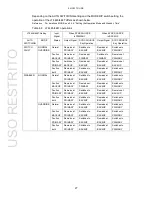
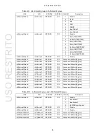
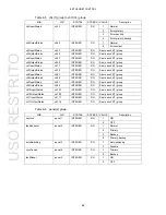
Table 6-1  fanUnit(1) group (LT 4447 only) 


Table 6-2  powerUnit1(2) group 


MIB 

OID 

SYNTAX 

ACCESS  VALUE 

Description 

powerUnit1Status 

powerUnit1.1  INTEGER 

RO 

Ejected (LT 4447 only) 

Error 

OK 

powerUnit1FanStatus 

(LT 4447 only) 

powerUnit1.2  INTEGER 

RO 

Stop 

Operation 


Table 6-3  powerUnit2(3) group 


MIB 

OID 

SYNTAX 

ACCESS  VALUE 

Description 

powerUnit2Status 

powerUnit2.1  INTEGER 

RO 

Ejected (LT 4447 only) 

Error 

OK 

powerUnit2FanStatus 

(LT 4447 only) 

powerUnit2.2  INTEGER 

RO 

Stop 

Operation 


Table 6-4  ch1(4) group to ch3(6) group 


MIB 

OID 

SYNTAX 

ACCESS  VALUE 

Description 

ch1InputStatus 

ch1.1 

INTEGER 

RO 

Normal 

Error-primary 

Error-backup 

Error-primary-backup 

ch2InputStatus 

ch2.1 

INTEGER 

RO 

Same as ch1(4) group 

ch3InputStatus 

ch3.1 

INTEGER 

RO 

Same as ch1(4) group 

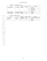
MIB 

OID 

SYNTAX 

ACCESS 

VALUE 

Description 

fanUnitStatus 

fanUnit.1 

INTEGER 

RO 

Ejected 

Stop 

Operation 


USO 

RESTRITO
Summary of Contents for LT 4446

Page 1: ...LT 4446 LT 4447 CHANGEOVER INSTRUCTION MANUAL USO RESTRITO ...

Page 2: ...eristics 5 2 3 4 Input Signals 6 2 3 5 Signal Switching 6 2 3 6 Fault Detection 7 2 3 7 Alarm Detection 8 2 3 8 Key Lock 8 2 3 9 External Control Connectors 8 2 3 10 Power Supply Unit LT 4447 only 8 2 3 11 Fan Unit LT 4447 only 8 2 3 12 General Specifications 9 3 PANEL DESCRIPTION 10 3 1 Front Panel 10 3 2 Rear Panel 11 3 3 Top Panel 12 4 HOW TO USE 13 4 1 Attaching the Cover Inlet Stopper 13 4 2 ...

Page 3: ...larm Indications 29 5 REMOTE CONTROL 31 6 ETHERNET CONTROL 33 6 1 SNMP Configuration Software 33 6 1 1 Installation 33 6 1 2 Uninstallation 35 6 1 3 Connection 36 6 1 4 Window Explanations 37 6 2 SNMP 39 6 2 1 SNMP Version 39 6 2 2 SMI Definitions 39 6 2 3 HOW TO USE 39 6 2 4 Enterprise MIB 40 6 2 5 Specific Trap Type 46 7 MAINTENANCE LT 4447 ONLY 47 7 1 Cleaning the Air Filters When they are dirt...

Page 4: ...If you have any questions about the contents of this manual please contact your local LEADER agent Symbols and Terms The following symbols and terms are used in this instruction manual and on the instrument to indicate important warnings and notes Symbol This symbol appears in this instruction manual and on the instrument to indicate an area where improper handling could result in personal injury ...

Page 5: ...within it If there is a possibility that the instrument has condensation within it wait for approximately 30 minutes before turning on the power Operating Humidity Range Use this instrument in an environment whose relative humidity is 90 RH or less where there is no threat of condensation forming Also do not operate this instrument with wet hands Doing so could lead to electric shock or fire Do No...

Page 6: ... to protect the user and the instrument from electric shock Ensure that the product is properly grounded for safe operation Warnings Concerning the Panel Sections of the panel are made out of glass If the glass breaks the broken glass may lead to injury Do not apply a strong shock to the panel cut it with sharp metal or damage it in any similar manner Cautions Concerning the Input and Output Conne...

Page 7: ...h mild detergent and wipe gently While cleaning make sure that foreign materials such as water and detergent do not enter the product If liquid or a metal object enters into the instrument fire or electric shock may result About the European WEEE Directive This instrument and its accessories are subject to the European WEEE Directive Follow the applicable regulations of your country or region when...

Page 8: ...anufactured under the strictest quality control guidelines LEADER shall not be obligated to furnish the following free services during the warranty period 1 Repair of malfunction or damages resulting from fire natural calamity or improper voltage applied by the user 2 Repair of a product that has been improperly repaired adjusted or modified by personnel other than a factory trained LEADER represe...

Page 9: ...le input voltage Input Connector Maximum Allowable InputVoltage CHANNEL 1 to 3 PRIMARY BACKUP 5V CHANNEL 4 to 10 PRIMARY BACKUP 1 5V CHANNEL 11 PRIMARY BACKUP 0V 5V TTL 1 3 3 Mechanical Shock This instrument contains sensitive components so it may be damaged if it is dropped or otherwise exposed to a strong shock 1 3 4 Electrostatic Damage Electronic components can be damaged by static discharge S...

Page 10: ...lays are used to switch between the primary signals and backup signals of channels 1 to 3 High speed electronic switches are used to switch between the primary signals and backup signals of channels 4 to 11 Selecting the Input Signal On channels 1 to 3 you can select SDI signals 3G HD SD NTSC PAL black burst signals or HD tri level sync signals On channels 4 to 8 you can select NTSC PAL black burs...

Page 11: ...for the user defined fault detection level can be read as status information IP address configuration software is included Compatible with Windows 7 32 bit and 64 bit Combining with an LT 4600 or LT 4110 The depths of the LT 4446 and the LT 4600 MULTIFORMAT VIDEO GENERATOR are the same The same holds true for the LT 4447 and the LT 4110 SYNC GENERATOR This makes it easy to wire and operate the dev...

Page 12: ...rs Primary Input Connectors Ch1 to 10 10 input connectors 75 Ω BNC connectors Ch11 1 input connector TTL 75 Ω BNC connector Backup Input Connectors Ch1 to 10 10 input connectors 75 Ω BNC connectors Ch11 1 input connector TTL 75 Ω BNC connector Output Connectors Ch1 to 10 10 output connectors 75 Ω BNC connectors Ch11 1 output connector 5 V CMOS 75 Ω BNC connector 2 3 3 I O Characteristics Ch1 to 3 ...

Page 13: ...sync signal SD SDI signal 270 Mb s HD SDI signal 1 485 Gb s 3G SDI signal 2 97 Gb s Ch4 to 8 NTSC black burst signal PAL black burst signal HD tri level sync signal Ch9 and 10 AES EBU Digital Audio Signal Ch11 Word clock Signal TTL 2 3 5 Signal Switching Switching Method Ch1 to 3 Relays Ch4 to 11 Electrical switches Switch Time from the Panel Ch1 to 3 10 ms or less Ch4 to 11 100 ns or less Switch ...

Page 14: ...al 631 to 794 mV 1000 mV Word clock signal 1515 to 1907 mV 2400 mV High level 1 NTSC Black Burst Signal 210 to 264 mV 286 mV PAL Black Burst Signal 220 to 277 mV 300 mV HD Tri Level Sync Signal 379 to 535 mV 600 mV SD SDI signal 270 Mb s 505 to 713 mV 800 mV HD SDI signal 1 485 Gb s 505 to 713 mV 800 mV 3G SDI signal 2 97 Gb s 505 to 713 mV 800 mV AES EBU Digital Audio Signal 734 to 924 mV 1000 mV...

Page 15: ...OURCE AUTO SWITCHING RESET Output SYNC SOURCE FAULT Connector 9 pin D sub female Locking Screws Ethernet Port 4 40 inch screws Use SNMPv1 control TRAP STATUS Compliant Standards 10BASE T 100BASE TX auto switching Connector RJ 45 SNMP Read Community LDRUser SNMP Write Community LDRAdm SNMP Trap Community LDRUser SNMP negotiation AUTO USB Port Use IP address configuration Compliant Standards USB 1 1...

Page 16: ... Category II Pollution Degree 2 Power Requirements Redundancy Supported Voltage 90 to 250 VAC Frequency 50 60 Hz Power Consumption LT 4446 25W max LT 4447 50W max Dimensions LT 4446 426 W 44 H 400 D mm excluding protrusions LT 4447 426 W 88 H 450 D mm excluding protrusions Weight LT 4446 4 0 kg excluding rack support LT 4447 8 0 kg excluding rack support Accessories Power cord 2 Cover Inlet stoppe...

Page 17: ...ULT to switch the output signal automatically Select DISABLED to not switch the output signal automatically 4 7 3 5 FAULT INDICATOR The LEDs blink when faults are detected in the input signals Press RESET to reset alarm indications and faultindications 4 8 1 6 KEY LOCK The LEDs indicate the key lock on off state You can press the key to turn the key lock on and off Key lock turns on automatically ...

Page 18: ...nal Connect to an external ground 5 ETHERNET Ethernet port You can use this port to monitor the LT 4446 4447 using SNMP 6 6 REMOTE Remote control connector You can use this connector to performfunctions such as configuring the LT 4446 4447 and transmitting fault information 5 7 Serial label The serial number is printed on this label 8 AC INPUT 1 AC INPUT 2 AC inlet Attach the included cover inlet ...

Page 19: ...panel description No Name Description Reference 1 DIP switch cover Remove the four screws to access the DIP switches You can use the DIP switches to configure the LT 4446 4447 An explanationof the DIP switch settings is printed on the back side of the cover 4 5 USO RESTRITO ...

Page 20: ... follow the procedure below Attaching the Cover Inlet Stopper 1 Cover the power cord with the cover inletstopper 2 Push the cover inlet stopper until you hear a click to attach it to the AC inlet 3 Check that the cover inlet stopper is securely attached to the AC inlet Removing the Cover Inlet Stopper 1 Release the lock by using two fingers to press the cover inlet stopper levers 2 Pull the cover ...

Page 21: ...ps head screwdriver 2 torque the screws to 63 cN m for the LT 4446 and 147 cN m for the LT 4447 Be sure to provide additional support for the body of the instrument If you only use the rack supports to mount the instrument the instrument case may deform or fall LT 4446 LT 4447 Figure 4 1 Attaching Rack Supports USO RESTRITO ...

Page 22: ...s Standby mode When on standby the SYNC SOURCE PRIMARY AUTO SWITCHING SWITCH FAULT and KEY LOCK ON and OFF LEDs light and the AUTO SWITCHING DISABLED LED blinks The LT 4446 4447 does not function when it is in this state Figure 4 2 Standby mode Leaving Standby Mode When the LT 4446 4447 leaves Standby mode the SYNC SOURCE PRIMARY AUTO SWITCHING SWITCH FAULT and KEY LOCK ON LEDs light The LT 4446 4...

Page 23: ...to PRIMARY 4 5 DIP Switch Settings Use the DIP switches on the top panel to configure the LT 4446 4447 To access the DIP switches first remove the DIP switch cover by unscrewing its four screws To avoid errors do not connect the signals until you have completed making all the settings The settings specified by DIP switches take effect after you restart the LT 4446 4447 Be sure to restart the LT 44...

Page 24: ... Ch4 High speed SW2 OFF Ch5 High speed SW3 OFF Ch6 High speed SW4 OFF ERROR DETECTIO N SPEED S1 Bottom row SW1 OFF Ch7 High speed SW2 OFF Ch8 High speed SW3 OFF Ch9 High speed SW4 OFF Ch10 High speed SW5 OFF Ch11 High speed SW6 to 8 OFF Fault detection reference settings VREF LOW S5 All ON VREF LOW VREF HIGH S9 All OFF Fault detection level settings user defined USER ADJUST1 RV9 USER ADJUST2 RV10 ...

Page 25: ...18 4 HOW TO USE 4 5 2 Setting the Input Signals Set the input signal for each channel The factory default setting is no input signal for all channels Figure 4 6 Input signal settings USO RESTRITO ...

Page 26: ...i level sync signal 720P 60 ON ON OFF OFF OFF OFF X X Ch1 to 8 720P 59 94 ON ON OFF ON OFF OFF X X 720P 50 ON ON OFF OFF ON OFF X X 720P 30 ON ON OFF ON ON OFF X X 720P 29 97 ON ON OFF OFF OFF ON X X 720P 25 ON ON OFF ON OFF ON X X 720P 24 ON ON OFF OFF ON ON X X 720P 23 98 ON ON OFF ON ON ON X X 1080i 60 OFF OFF ON OFF OFF OFF X X 1080i 59 94 OFF OFF ON ON OFF OFF X X 1080i 50 OFF OFF ON OFF ON O...

Page 27: ...xed to 70 ms or less Fault detection on channels 1 to 3 is performed on the signal level If you select low speed fault detection is performed on the signal level If you set the input signal type to user defined select low speed If you select high speed fault detection is performed on whether the signal is present If you select high speed you do not need to set the fault detection reference The fac...

Page 28: ...or less SW2 Ch5 1 5 H or less 60 ms or less SW3 Ch6 1 5 H or less 60 ms or less SW4 Not used 1 Bottom row SW1 Ch7 1 5 H or less 60 ms or less SW2 Ch8 1 5 H or less 60 ms or less SW3 Ch9 6 us or less 60 ms or less SW4 Ch10 6 us or less 60 ms or less SW5 Ch11 60 us or less 60 ms or less SW6 Not used 1 SW7 Not used 1 SW8 Not used 1 1 1 Leave unused switches in the OFF position USO RESTRITO ...

Page 29: ...etection reference settings 1 Depending on the instrument that you are using there will be deviations in the fault detection level within the ranges given in this table Number Input Signal Fault Detection Level 1 Normal Level VREF LOW VREF HIGH SW1 NTSC black burst signal 180 to 227 mV 210 to 264 mV 286mV SW2 PAL black burst signal 190 to 238 mV 220 to 277 mV 300mV SW3 HD tri level sync signal 337...

Page 30: ...Set DIP switches SW1 and SW3 of CH 1 S2 to ON 2 Restart the LT 4446 4447 to apply the new settings 3 Connect between the input signal and PRIMARY an attenuator with an appropriate attenuation 3 to 6 dB for detecting faults 4 While turning USER ADJUST1 RV9 press RESET repeatedly and stop when the PRIMARY FAULT INDICATOR LED turns off 5 Slowly turn the USER ADJUST1 trimmer backwards and stop when th...

Page 31: ...MAL Leave this set to NORMAL under standard operating circumstances Reference For details on the SYNC SOURCE key see section 4 7 2 Switching the Output Signal For details on the AUTO SWITCHING key see section 4 7 3 Setting Automatic Signal Switching Setting the Standby Time You can select the length of time that the LT 4446 4447 waits from the time that it turns ON to the time that it begins opera...

Page 32: ...ctor Figure 4 11 Signal I O The types of signals that you can apply differ depending on the channel as shown below Table 4 7 Operation mode and standby time settings Input Channel Input Signal Signal Switching Method Ch1 to 3 NTSC black burst signal PAL black burst signal HD tri level sync signal SD SDI signal 270 Mb s HD SDI signal 1 485 Gb s 3G SDI signal 2 97 Gb s Relays Ch4 to 8 NTSC black bur...

Page 33: ...ever you may not be able to switch the signal depending on the LT 4446 4447 state For details see section 4 7 3 Setting Automatic Signal Switching SYNC SOURCE is set to PRIMARY immediately after the LT 4446 4447 turnsON Figure 4 13 SYNC SOURCE 4 7 3 Setting Automatic Signal Switching In the AUTO SWITCHING area select whether the output signal will beswitched automatically when a fault is detected ...

Page 34: ...UP Remains at BACKUP Remains at BACKUP Remains at BACKUP Fault on both Remains at PRIMARY Switches to BACKUP Remains at BACKUP Switches to PRIMARY DISABLED NORMAL Normal Remains at PRIMARY Switches to BACKUP Remains at BACKUP Switches to PRIMARY Fault on BACKUP Remains at PRIMARY Remains at PRIMARY Remains at BACKUP Switches to PRIMARY Fault on PRIMARY Remains at PRIMARY Switches to BACKUP Remains...

Page 35: ...ARY or BACKUP channels For example if a fault is detected in PRIMARY channel 1 the LEDs light or blink as follows Figure 4 15 Fault indication 1 If a fault is detected in BACKUP channel 3 the LEDs light or blink as follows Figure 4 16 Fault indication 2 Resetting Fault Indications Once a fault is detected even if the input signals return to normal the FAULT and FAULT INDICATOR LEDs will continue t...

Page 36: ... If the LED does not turn off even after you press RESET contact your local LEADER agent Figure 4 18 Output alarm indications Power Supply Alarm Indications The ALARM POWER LED or the ALARM on the power supply unit lights in red in the following situations If the LED lights in red even when you turn on both power supplies contact your local LEADER agent When an error occurs in the power supply out...

Page 37: ...tion LT 4447 only The FAN LED lights in red when an error occurs in the fan unit on the rear panel If the LED lights even when the fan is installed properly contact your local LEADER agent Figure 4 21 Fan alarm indication USO RESTRITO ...
Page 38: ...AULT using keys to enable remote control 2 SYNC SOURCE I Each time a low level signal is applied SYNC SOURCE switches between PRIMARY and BACKUP 3 SYNC SOURCE PRIMARY O Transmits a high level signal when SYNC SOURCE is set to PRIMARY 4 SYNC SOURCE BACKUP O Transmits a high level signal when SYNC SOURCE is set to BACKUP 5 FAULT INDICATOR O Transmits a high level signal when a fault is detected in P...

Page 39: ...ple 1 I Connect a switch to apply a low level signal Connect one side of the switch to the remote connector and the other side to ground 2 6 3 O Connect an LED so that it will light when a high level signal is transmitted Connect the anode to the remote connector and the cathode to ground 4 5 O 7 O USO RESTRITO ...

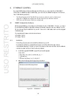
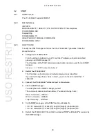
Page 40: ...st install the SNMP configuration software hereafter referred to as the software in your PC and connect the LT 4446 4447 to your PC Have a PC USB cable A B and the supplied CD ROM ready The supported Windows versions are as follows Windows 7 32 bit Windows 7 64 bit 6 1 1 Installation Follow the procedure below to install the software in your PC To update the software uninstall the old version and ...

Page 41: ...HERNET CONTROL 3 When the following window appears select the installation folder and click Next Figure 6 2 Installation 2 4 When the following window appears click Next Figure 6 3 Installation 3 USO RESTRITO ...

Page 42: ...se When the installation is complete two MIB files LT4446 MIB txt and LT4447 MIB txtare created on the desktop Figure 6 4 Installation 4 6 1 2 Uninstallation To uninstall the software select lt4446 in Programs and Features of Control Panel and click Uninstall Figure 6 5 Uninstallation USO RESTRITO ...
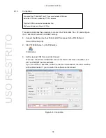
Page 43: ... COM Port and clickConnect When the connection is established the Connect button becomes unavailable and GET and SUBMIT become available If you turn off the LT 4446 4447 while a connection is established the communication will be disconnected If you do restart the software and reconnect Figure 6 6 Connection To connect the LT 4446 4447 to a PC you must install a USB driver Install the VCP driver p...

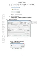
Page 44: ...ars click OK Figure 6 7 Configuration complete 6 Restart the LT 4446 4447 The network settings are applied after you restart the LT4446 4447 6 1 4 Window Explanations Figure 6 8 Window explanation About lt4446 Right click the title bar to use this command It displays the software version Figure 6 9 Software version USO RESTRITO ...

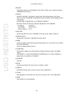
Page 45: ...er the values and then click Set Software Version Pressing GET shows the LT 4446 4447 firmware version SNMP Set the IP address of the TRAP transmission destination If you set this to 0 0 0 0 TRAPs will not be transmitted The factory default setting is 0 0 0 0 Configuration Pressing GET retrieves the current Machine Network Software Version and SNMP values Click SUBMIT to confirm the NETWORK and SN...

Page 46: ...NMP manager Reference 6 1 SNMP Configuration Software 2 Restart the LT 4446 4447 The IP address subnet mask and default gateway values takeeffect If you did not change these values in step 1 you do not need to restart the LT 4446 4447 3 Connect the LT 4446 4447 s Ethernet port to thenetwork 4 Start an SNMP manager You must provide the SNMP manager yourself The community names are shown below You c...

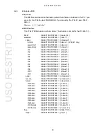
Page 47: ...NTIFIER status 6 ch4 OBJECT IDENTIFIER status 7 ch5 OBJECT IDENTIFIER status 8 ch6 OBJECT IDENTIFIER status 9 ch7 OBJECT IDENTIFIER status 10 ch8 OBJECT IDENTIFIER status 11 ch9 OBJECT IDENTIFIER status 12 ch10 OBJECT IDENTIFIER status 13 ch11 OBJECT IDENTIFIER status 14 panel OBJECT IDENTIFIER standard 2 remote OBJECT IDENTIFIER standard 3 format OBJECT IDENTIFIER standard 4 ch1format OBJECT IDEN...

Page 48: ... RO 1 Stop 2 Operation Table 6 3 powerUnit2 3 group MIB OID SYNTAX ACCESS VALUE Description powerUnit2Status powerUnit2 1 INTEGER RO 1 Ejected LT 4447 only 2 Error 3 OK powerUnit2FanStatus LT 4447 only powerUnit2 2 INTEGER RO 1 Stop 2 Operation Table 6 4 ch1 4 group to ch3 6 group MIB OID SYNTAX ACCESS VALUE Description ch1InputStatus ch1 1 INTEGER RO 1 Normal 2 Error primary 3 Error backup 4 Erro...

Page 49: ...h8InputStatus ch8 1 INTEGER RO Same as ch4 7 group ch8OutputStatus ch8 2 INTEGER RO Same as ch4 7 group ch9InputStatus ch9 1 INTEGER RO Same as ch4 7 group ch9OutputStatus ch9 2 INTEGER RO Same as ch4 7 group ch10InputStatus ch10 1 INTEGER RO Same as ch4 7 group ch10OutputStatus ch10 2 INTEGER RO Same as ch4 7 group ch11InputStatus ch11 1 INTEGER RO Same as ch4 7 group ch11OutputStatus ch11 2 INTE...

Page 50: ...matStatus2 ch1format 2 INTEGER RO 1 Disable 2 60Hz 1080i 720P 3 59 94Hz 1080i 720P 4 50Hz 1080i 720P 5 30Hz 1080P 720P 6 29 97Hz 1080P 720P 7 25Hz 1080P 720P 8 24Hz 1080P 720P 9 23 98Hz 1080P 720P ch1FormatStatus3 ch1format 3 INTEGER RO 1 Disable 2 HD SDI 3 3G SDI ch2FormatStatus1 ch2format 1 INTEGER RO Same as ch1format 1 group ch2FormatStatus2 ch2format 2 INTEGER RO Same as ch1format 1 group ch2...

Page 51: ...format 4 group ch6FormatStatus3 ch6format 3 INTEGER RO Same as ch4format 4 group ch7FormatStatus1 ch7format 1 INTEGER RO Same as ch4format 4 group ch7FormatStatus2 ch7format 2 INTEGER RO Same as ch4format 4 group ch7FormatStatus3 ch7format 3 INTEGER RO Same as ch4format 4 group ch8FormatStatus1 ch8format 1 INTEGER RO Same as ch4format 4 group ch8FormatStatus2 ch8format 2 INTEGER RO Same as ch4form...

Page 52: ...e 6 User define 1 7 User define 2 8 Word clock ch11FormatStatus2 ch11format 2 INTEGER RO 1 Disable ch11FormatStatus3 ch11format 3 INTEGER RO 1 Disable Table 6 12 target 1 group MIB OID SYNTAX ACCESS VALUE Description managerIp target 1 IP ADDRESS R W Trap transmission destination trapAction target 2 INTEGER R W 1 Enable 2 Disable USO RESTRITO ...

Page 53: ...utStatus ch4 outputStatus 11 ch5Status Channel 5 status change detection ch5 inputStatus ch5 outputStatus 12 ch6Status Channel 6 status change detection ch6 inputStatus ch6 outputStatus 13 ch7Status Channel 7 status change detection ch7 inputStatus ch7 outputStatus 14 ch8Status Channel 8 status change detection ch8 inputStatus ch8 outputStatus 15 ch9Status Channel 9 status change detection ch9 inp...

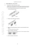
Page 54: ...turned on 1 Turn the sub panel screws counterclockwise and remove the sub panel You can turn the screws by hand 2 Remove the two air filters from the subpanel 3 Wash the air filter with mild detergent and water or remove the dust with a vacuum cleaner If you wash the filters with water dry them 4 Attach the air filters to the sub panel Attach them to the positions shown below There is no front or ...

Page 55: ...e every three years The fan unit on the rear panel is a consumable component If an error occurs or if three years have passed since the previous replacement replace it by following the procedure below You can replace them while the power is turned on Replacement Parts For details contact your nearest LEADER agent Part No Name Specifications Quantity Used 0218100005 LP 2181 FAN UNIT 1 Replacement P...

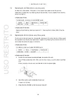
Page 56: ...a replacement unit contact your local LEADER agent Part No Name Specifications Quantity Used 0218000001 LP 2180 POWER UNIT 2 Replacement Procedure This section provides an example on how to replace power supply unit POWER 2 while leaving power supply unit POWER 1 turned on 1 Flip the power switch of POWER 2 to the off side POWER 2 ALARM lights 2 Turn the sub panel screws counterclockwise and remov...

Page 57: ... unit Check that vertical orientation The label should be on top When it is inserted properly the ALARM LED turns on 5 Tighten the power supply unit screws and attach the sub panel Torque the screws to 147 cN m 6 Flip the power switch of POWER 2 to the on side and check that the ALARM LED turns off USO RESTRITO ...

Page 58: ...用期限 只要遵守与本产品有关的安全和使用上的注意事项 从制造日算起在数 字所表示的年限内 产品不会产生环境污染和对人体 财产的影响 产品适当使用后报废的方法请遵从电子信息产品的回收 再利用相关法令 详细请咨询各级政府主管部门 产品中有毒有害物质或元素的名称及含量 部件名称 Parts 有毒有害物质或元素 Hazardous Substances in each Part 铅 Pb 汞 Hg 镉 Cd 六价铬 Cr Ⅵ 多溴联苯 PBB 多溴二苯醚 PBDE 实装基板 主体部 开关电源 风扇 外筐 线材料一套 附件 包装材 备注 表示该有毒有害物质在该部件所有均质材料中的含量均在SJ T11363 2006 规定的限量要求以下 表示该有毒有害物质或元素至少在该部件的某一均质材料中的含量超出SJ T11363 2006 标准规定的限量要求 Ver 1 USO RESTRITO ...

Page 59: ...LEADER ELECTRONICS CORP 2 6 33 Tsunashima Higashi Kohoku ku Yokohama 223 8505 Japan PHONE 81 45 541 2123 FAX 81 45 541 2823 http www leader co jp May 1 2014 Ver 1 USO RESTRITO ...

Reviews: