Leader Evaporator Co., Inc.
49 Jonergin Drive
Swanton, VT 05488
Tel: 802-868-5444 www.leaderevaporator.com
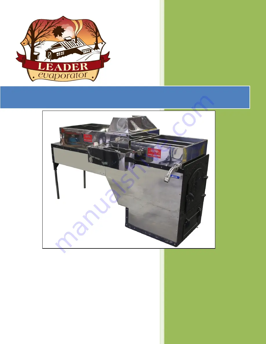
WSE Evaporator Manual
Page 1: ...Leader Evaporator Co Inc 49 Jonergin Drive Swanton VT 05488 Tel 802 868 5444 www leaderevaporator com WSE Evaporator Manual...
Page 2: ...IVING YOUR EVAPORATOR 9 SUGAR HOUSE SETUP 10 FOUNDATION FOR THE ARCH 12 SETTING THE ARCH ON THE FOUNDATION 12 INSULATING THE ARCH 13 Cementing of Insulation Board and Bricks 14 Insulation Board 15 Ins...
Page 3: ...ACK 38 NOTES 38 ATTACHMENT 1 HYDROMETER USAGE 39 HYDROMETER FUNCTION 39 USE OF A HYDROMETER 39 Preparing A New Hydrometer For Use 39 Using The Hydrometer 39 ATTACHMENT 2 INSTALLATION AND USAGE OF THE...
Page 4: ...As the syrup pan boils the sap becomes denser The flue pan sap is pushed into the syrup pan making sap in the first syrup pan compartment less dense The sap from the first syrup pan compartment is pu...
Page 5: ...he flue pan each time you fire the evaporator 2 Add defoamer primarily to the flue pan Modify this only under certain conditions 3 The estimated usage for a 2 foot wide WSE is 3 drops The usage may ne...
Page 6: ...r is defined as the draw off assembly will be on the right front of the syrup pan when standing facing the firing door The Leader WSE Evaporator consists are the following parts ITEM LEADER ORDER DESC...
Page 7: ...Qty 2 Wire tied to inside rear of arch 77021 Flue Brush Rod 8 60069 6 60071 8 Rod end is threaded to allow mounting of flue brush Flue Brush 60058 OPTIONAL SETUP MATERIAL ADDITIONAL SPARE PARTS AND O...
Page 8: ...less Steel Smoke Stack 3 x 10 5210S Stainless Steel Base Stack 542410L Upgrade Butterfly 1 WSE 390002 Valve allows for isolating the flue pan from the syrup pan so the flue pan does not need to be dra...
Page 9: ...LEADER EVAPORATOR WSE Evaporator 2018 Page 8 DIAGRAM OF THE WSE EVAPORATOR...
Page 10: ...es option SUGGESTED TOOLS 7 16 box open end wrench Phillips screwdriver Utility knife Plumb bob Drill Drill bits Bricking trowel Measuring tape Marker mark roof material Level 4 Brick saw RECEIVING YO...
Page 11: ...sidered The requirements for the setup of the WSE evaporator may not be adequate if in the future additional or larger equipment will be needed If assistance is needed in determining possible future r...
Page 12: ...ind any additional items equipment ex packaging supplies canner table s chairs and where they will be located in the sugar house 1 Front of the arch six 6 feet a Allows room for firing and cleaning ou...
Page 13: ...it b The front of the arch should be on the open side of the Ash Pit c Center the firebox on the Ash Pit foundation 2 The pipe legs are wire tied to the inside rear of the arch for transport Remove th...
Page 14: ...order is as follows 1 Left Side Insulation 2 Right Side Insulation 3 Back Insulation 4 Insert the grates 5 Front Insulation 6 Top View Insulation starting with under the Grate Shelf then the Incline...
Page 15: ...ing sheets at the top of the arch are cut to leave a gap between the sheet top and the bottom of the arch rail Cementing of Insulation Board and Bricks 1 Place a temporary support at the bottom of the...
Page 16: ...5 L3 31 5 9 75 L4 Top 36 Bottom 29 5 12 Down 2 from Top then cut on angle to 29 5 L5 25 9 5 Top cutout 1 5 L 0 5 W Bottom cutout 1 L 0 5 W The following are dimensions for the parts labeled above Alw...
Page 17: ...so one is on each side of the arch and the other is approximately in the middle Obtain a piece of C flute cardboard most common type of cardboard approximately 20 x 18 Fold it into thirds along the le...
Page 18: ...it above the grates The following are dimensions for the parts labeled above Always dry fit the parts prior to cementing to ensure proper fit Print ID Length Width Notes TV1 22 25 9 25 Not Shown under...
Page 19: ...Quantity Needed NOTES FB Full 9 000 4 500 2 500 4 HB Half 9 000 4 500 1 250 22 HHB Half 4 500 4 500 1 250 3 BL1 Half 6 625 4 500 1 250 1 BL2 Half 9 000 4 500 1 250 1 Cutout 1 L 0 625 W BL3 Half top 6...
Page 20: ...ntity Needed NOTES FB Full 9 000 4 500 2 500 4 HB Half 9 000 4 500 1 250 22 HHB Half 4 500 4 500 1 250 3 BR1 Half 6 625 4 500 1 250 1 BR2 Half 9 000 4 500 1 250 1 Cutout 1 L 0 625 W BR3 Half top 6 125...
Page 21: ...t door They are placed so as to be above the grates NOTE NO bricks are placed around the draft door section Brick ID Brick Type Length Width Thickness Quantity Needed NOTES FB Full 9 000 4 500 2 500 1...
Page 22: ...s for easier illustration The arch sections are as follows The following are dimensions for the bricks labeled above Always dry fit the parts prior to cementing to ensure proper fit Brick ID Brick Typ...
Page 23: ...hickness Quantity Needed NOTES FB Full 9 000 4 500 2 500 1 BG1 Full 5 375 4 500 2 500 2 The following are dimensions for the bricks labeled above Always dry fit the parts prior to cementing to ensure...
Page 24: ...dry fit the parts prior to cementing to ensure proper fit NOTE The first row of bricks will overlap the bricks on the Incline Use cement to fill openings between the bricks Brick ID Brick Type Length...
Page 25: ...the groove in the ferrule to the projection on the Teflon gasket 2 Place the clamp groove over the assembled ferrules and Teflon gasket Ensure the gasket is properly seated in the ferrule prior to pl...
Page 26: ...installed left draw bracket on left right draw bracket on right 4 Slide the float box brace into the bracket where the thumbscrew is installed Ensure the float box ferrule is facing the flue pan ferr...
Page 27: ...p and flue pans 11 Install the U tube a Place a 1 Teflon gasket onto the ferrule of the flue pan to be connected to the U tube same side as the rear ferrule on the syrup pan b Place the U tube over th...
Page 28: ...p over the ferrules and gasket Position the clamp so the bolt is on the flue side of the evaporator and the wing nut faces down Align the draw off valve assembly so it is directed fully down Close the...
Page 29: ...it overlaps the bridge tube Tighten the clamp d Slide a 24 band clamp onto the other end of the hose connector Place your sap source line into the connector and tighten the band clamp to hold your lin...
Page 30: ...of the flue pan with the wide part of the guard toward the flue pan c Raise the rear of the splash guard to allow for the splash guard lip to slide under the front edge of the flue pan d Lower the sp...
Page 31: ...tion is the upper top section 1 When installing a roof jack refer to the LEADER CUSTOMIZED ROOF JACK document 2 If not using a roof jack make a hole at the point marked on the inside of the roof in th...
Page 32: ...stack cover will minimize the rain and moisture entering the stack and arch When installing a stack cover refer to the LEADER STACK COVER document 2 If a roof jack is used a Insert one piece of stack...
Page 33: ...the pans remains at the 2 to 3 inch level 4 Check all equipment a No leaks at fittings b Pans are boiling evenly c Valves work properly d Draft is correct Draft is correct when The boil is the same i...
Page 34: ...ow the grates h If present open cupola thimbles and hood condensate drains 2 If this startup is for a new evaporator or for the first time of the season go to the Section titled MAKING SYRUP It is rec...
Page 35: ...u tube connection ferrule RE ASSEMBLE NOTE LEADER EVAPORATOR offers an upgrade to the WSE LEADER EVAPORATOR part number 390002 which replaces the u tube with a connector including a butterfly valve If...
Page 36: ...add three 3 drops of defoamer based on ATMOS 300 to the flue pan on the float box side Defoamer should be added close to the inlet from the float box Open the sap feed valve on your sap source line 6...
Page 37: ...rom the last firing to embers and to flood the arch so ensure there is adequate volume left prior to the last firing i 2X4 WSE will require 20 gallons of sap after the last firing ii 2X6 WSE will requ...
Page 38: ...ng and keep at that level for one hour and the scale is noted to dissolve d Wearing protective gloves brush the loose scale e If scale is removed flush the pans with water If the scale is thick you ma...
Page 39: ...then set the syrup pan right side up on the 2X4s 10 Cover the pans and arch with plastic or a tarp BEGINNING OF SEASON STARTUP 1 Remove the cover and take the pans and 2X4s off from the arch 2 Install...
Page 40: ...spare Preparing A New Hydrometer For Use 1 Unpack the hydrometer from its tube or box 2 Carefully inspect the hydrometer for any breakage If you suspect any cracks fill your test cup with hot water an...
Page 41: ...the liquid the syrup is heavy and will need to be diluted with sap 7 Refer to the chart to determine if your syrup is light or heavy If the reading is higher than the number on the table your syrup is...
Page 42: ...ow of sap to the flue pan INSTALLATION NOTE Do NOT install this valve onto the pans without first disassembling If not fully disassembled the rubber section cannot be aligned properly and will be dama...
Page 43: ...t across or 90o to the assembly A way of doing this is to use a marker and mark the top side of the shaft and the same side as the flapper In order to make the completion of the assembly easier it is...
Page 44: ...the shaft pointing in the same direction as the flapper valve If you have maintained the flapper parallel to the rubber assembly then the handle should be mounted at right angles to the valve Tighten...
Page 45: ...Slide the float box support into the syrup box bracket b Reconnect the upgrade assembly by securing with a Teflon gasket and clamp c Reconnect the draw off assembly with a Teflon gasket and clamp d Cl...