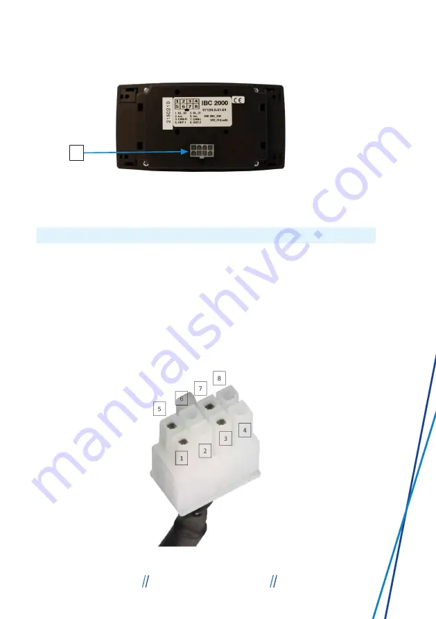
background image

4

Fig. 2: 

LPS II remote display back

4 Connector for Molex plug (8-PIN)

5.1 PIN assignment

Molex connector (8-PIN)

The Molex connector (8-PIN) is used to connect the LPS II remote display to
the LPS II.

Fig. 3: 

Molex connector PIN assignment

7

LEAB Automotive GmbH

Thorshammer 6

24866 Busdorf

LEAB Automotive GmbH

5 About this product

Summary of Contents for LPS II

Page 1: ...www leab eu USER MANUAL VERSION 5 LPS II REMOTE DISPLAY LEAB Automotive GmbH Thorshammer 6 24866 Busdorf ...

Page 2: ... Installation 9 7 Assembly 9 8 Operation 11 8 1 Switching on the unit 12 8 2 Switching off the unit 12 8 3 Quick selection 13 8 4 Charge status Status II 14 8 5 Operating data Status III 14 8 5 1 12 V output 14 8 5 2 12 V charging 15 8 5 3 230 V output 18 8 5 4 230 V Charging 19 8 5 5 Other settings 19 9 Disposal 26 10 EU Declaration of Conformity 26 Table of contents LEAB Automotive GmbH ...

Page 3: ...d Attention indicates that there is a possibility of material damage To avoid material damage follow the instruction CAUTION Danger that can lead to minor injuries Safety instructions with the signal word CAUTION indicate a hazard which if not avoided can result in minor or moderate injury Read the safety instructions carefully and follow them to avoid the hazard WARNING Hazards that can lead to s...

Page 4: ...applicable 2 Safety This user manual is designed to help you handle the unit safely Use the unit solely in accordance with its intended use Observe the safety instructions WARNING Risk of injury due to cable fire Using the unit at too high a voltage can cause a cable fire 1 Only use the unit within the specified voltage limits 2 1 Intended use The LPS II remote display is an optional accessory for...

Page 5: ...Excluding connection cable 1051009008 Including connection cable 1051009020 LPS II Remote Display Input voltage 9 8 V 32 0 V Operating temperature 20 C 70 C Installation depth from contact sur face to connections Approx 20 mm Connections Molex 8 pin IP rating IP21 Current consumption active 42 mA 12 V Current consumption standby 27 mA display inactive Current consumption off 26 µA Weight 0 16 kg D...

Page 6: ...vides an overview of all relevant operating data of the LPS II It shows the charge status of the LPS II as well as the operating data of the individual 12 V and 230 V outputs and inputs In addition the LPS II remote display allows you to activate or deactivate the individual 12 V and 230 V outputs simply by pressing a button 1 2 3 Fig 1 LPS II remote display front 1 Display 2 Housing panel 3 Rotar...

Page 7: ... 8 PIN 5 1 PIN assignment Molex connector 8 PIN The Molex connector 8 PIN is used to connect the LPS II remote display to the LPS II Fig 3 Molex connector PIN assignment 7 LEAB Automotive GmbH Thorshammer 6 24866 Busdorf LEAB Automotive GmbH 5 About this product ...

Page 8: ...31 Ground 6 NC Not assigned 7 CAN Bus Low 8 Output 2 M12 connector The M12 connector enables external devices or signals to be connected to the LPS II remote display Fig 4 M12 connector PIN assignment PIN Assignment 1 Battery positive 2 Battery positive 3 Ground 4 Can Bus High 5 Can Bus Low 8 LEAB Automotive GmbH Thorshammer 6 24866 Busdorf 5 About this product LEAB Automotive GmbH ...

Page 9: ... into the marked M12 connec tion on the back of the LPS II ð The unit is installed LPS II Remote Display Fig 5 LPS II remote display wiring diagram 7 Assembly WARNING Risk of injury due to improper work The use of unsuitable tools to cut out the mounting area and not wearing the necessary protective clothing can lead to injuries 1 Use suitable tools such as a jigsaw 2 Wear protective gloves during...

Page 10: ...ove the covers from the mounting holes of the unit slide the left and right housing panels to the side 4 Insert the unit into the mounting cut out 5 Mark the position of the fastening holes with a pin 6 Disconnect the connecting cable from the unit by removing the Molex con nector on the back of the LPS II remote display 7 Guide the connecting cable through the mounting cut out 8 Insert the Molex ...

Page 11: ...ttin gs Display settin gs Device information Error codes Service back Service Please contact our Servi c e P age www leab eu en support lps ii Error codes 12 V Charging Booster Solar Jumpstart back 12 V Jumps t art Jumpstart Voltage Current Power Time 0 00 V 0 00 A 0 W 0 0 min back Brightness Bright Medium Dark back Warning buz zer SoC SoC 20 SoC 10 Warning off zurück Dark Mode Turn on Turn off ba...

Page 12: ...isplay NOTE If the rotary knob of the LPS II remote display is not pressed for 30 s the display automatically switches back to the start screen status I 8 2 Switching off the unit To switch off the unit proceed as follows 1 Press and hold the rotary knob for at least 4 seconds ð A message appears on the display asking if you really wish to switch off the unit 2 Turn the rotary knob to select the Y...

Page 13: ... is switched on via the quick selection Quick selection 230 V Fig 9 Quick selec tion 230 V To activated or deactivate the 230 V output proceed as follows ü The LPS II remote display is switched on ü The start screen Status I is shown on the display of the unit 3 Turn the rotary knob to the right ð The quick selection 230 V is shown on the display of the unit 4 Switch on the 230 V output by pressin...

Page 14: ... for 12 V and 230 V Activated outputs and charging processes are indicated by a green coloured se lection field next to the respective menu item To get to the Status III display carry out the following step ü The LPS II remote display is switched on 1 Press the rotary knob 2 x in succession ð Status III is shown on the display of the unit You can now select a menu item by turning the rotary knob N...

Page 15: ...display turn the rotary knob to select the back menu item and press the rotary knob to confirm your menu item selection 8 5 2 12 V charging Fig 13 12 V char ging The operating data of the booster and the solar charge controller can be viewed and the emergency start func tion of the LPS II can be activated via the 12 V char ging menu To display the menu proceed as follows ü The LPS II remote displa...

Page 16: ...play of the unit In formation on the voltage applied the charging current and the power of the booster is displayed NOTE The booster cannot be activated via the display the display only provides insight into whether the booster is active or inactive Active inputs are indicated by a green coloured selection field next to the respective menu item of the 12 V charging menu NOTE If the rotary knob of ...

Page 17: ...6 12 V emer gency start Via the emergency start function a discharged starter battery can be recharged by the LPS II to such an extent that a starting process is possible again To activate the emergency start function of the LPS II proceed as follows ü The menu display 12 V charging is shown on the dis play of the unit 1 Turn the rotary knob to select the Emergency start menu item 2 Press the rota...

Page 18: ...ceed as follows ü The LPS II remote display is switched on ü Status III is shown on the display of the unit 1 Turn the rotary knob to select the 230 V output menu item 2 Press the rotary knob to confirm your menu item se lection ð 230 V output is shown on the display of the unit 3 Turn the rotary knob to select the AC output on off menu item 4 Press the rotary knob to confirm your menu item se lec...

Page 19: ... settings Fig 19 Other set tings The Other settings menu allows you to view the dis play settings unit information error codes and service information and adjust certain settings accordingly To display the Other Settings menu proceed as fol lows ü The LPS II remote display is switched on ü Status III is shown on the display of the unit 1 Turn the rotary knob to select the Other settings menu item ...

Page 20: ...ngs menu is shown on the display of the unit You can now select a menu item by turning the rotary knob NOTE To return to the previous display turn the rotary knob to select the back menu item and press the rotary knob to confirm your menu item selection 8 5 5 1 1 Language Fig 21 Language You can choose between German and English for the readings of the LPS II remote display To set the language of ...

Page 21: ...rge status of the LPS II To set the warning buzzer proceed as follows ü The LPS II remote display is switched on ü The Display Settings menu is shown on the display of the unit 1 Turn the rotary knob to select the Warning buzzer SoC menu item 2 Press the rotary knob to confirm your menu item se lection ð The Warning buzzer SoC menu is shown on the display of the unit 3 Turn the rotary knob to sele...

Page 22: ... the unit is operated in the dark To set the background colour proceed as follows ü The LPS II remote display is switched on ü The Display Settings menu is shown on the display of the unit 1 Turn the rotary knob to select the Dark Mode menu item 2 Press the rotary knob to confirm your menu item se lection ð The Dark Mode menu is shown on the display of the unit 3 Turn the rotary knob to select one...

Page 23: ...enu items 4 Press the rotary knob to confirm your menu item se lection ð The selected menu item turns green The brightness of the display is now set NOTE To return to the previous display turn the rotary knob to select the back menu item and press the rotary knob to confirm your menu item selection 8 5 5 1 5 Dim after Fig 25 Dim after The Dim after menu allows you to set the time of in activity af...

Page 24: ...on The Unit Information display shows the information on the serial number and the version numbers of the hardware and firmware of the LPS II as well as the ver sion number of the firmware of the LPS II remote display IBC To display the Unit Information menu proceed as fol lows ü The LPS II remote display is switched on ü The Other Settings menu is shown on the display of the unit 1 Turn the rotar...

Page 25: ... Error Codes is shown on the display of the unit You can now read the current error codes ð Look in the LPS II user manual for the current error code and follow the instructions TIP You can also find error codes and FAQs on the Internet on our LPS II support website To do this either follow the QR code of the Service menu display on the LPS II remote display directly or in the Service chapter of t...

Page 26: ...ur menu item se lection ð Service is shown on the display of the unit Visit the support website via the QR code or the web address www leab eu support lps ii 9 Disposal Dispose of the device in accordance with the Waste Elec trical and Electronic Equipment Regulations WEEE The system must not be disposed of with household waste Take it to a recycling point or return it to your point of sale 10 EU ...

Page 27: ...27 LEAB Automotive GmbH Thorshammer 6 24866 Busdorf LEAB Automotive GmbH 10 EU Declaration of Conformity ...

Page 28: ...orf Tel 49 0 4621 9 78 60 0 Fax 49 0 4621 9 78 60 260 info leab eu We make energy mobile It is prohibited to copy duplicate translate or otherwise pass on the content of this document to third parties without the express written permission of LEAB ...

Reviews: