background image

would like to do it for free, we just can't. We have a flat fee of $30 plus parts to repair a tuner (most

resistors and capacitors are included in that fee). The 68HC11 chip is the most expensive at $20. Relays are

$5 each. The 34064 is $5. The 78L05 is $1.

We will not attempt to repair any unit that has been soldered with acid core. We reserve the right to

refuse repair due to excessive problems or damage due to construction.

Before any unit is sent to us, you must first call to get return authorization (just so we know your unit

is on it’s way). All units sent in must be prepaid, either by check, money order or Credit Card unless

otherwise indicated. Package unit carefully and keep in mind we will use your packaging to return the unit

back to you. Include a description of what problem you are having and a phone number you can be reached at in

the evenings in case we have questions. Repairs average about 3 to 6 weeks, depending on the particular

problem.

Upgrades:

  We are continually trying to put more features in the software of the tuner. The current

version  of the software (QRP 1.0) was locked in with only 4 bytes (out of 512) of code space left.

If you have an idea of how the unit can be made better (in software or hardware), please send a

description of your upgrade. If we use it for the tuner, we'll send you a free upgrade. We can mention now that

we do not have enough code space to implement tuning from memory or adding an LCD display (but we're

working on it). Future upgrades will be available for about $10 with 68HC11 chip trade in. If you purchased

the kit from LDG, we will notify you when upgrades are available. If you did not purchase the unit from LDG

and you want to be on our mailing list, just drop us a card, letter, fax or e-mail.

Feedback:

  We encourage everyone who builds the kit to drop us a note (card, letter or e-mail preferred)

to let us know how well it works for you in your particular installation. This will ensure that we have

provided everyone with the best tuner kit possible and we can maintain a database of how well the tuner

performs.

8

Summary of Contents for QRP

Page 1: ...LDG Electronics 1445 Parran Road St Leonard MD 20685 Phone 410 586 2177 Fax 410 586 8475 e mail ldg radix net http www radix net ldg QRP Automatic Antenna Tuner Assembly Manual Ver 2 0c...

Page 2: ...our outputs to LEDs provide an indication of SWR and status Green indicates SWR of less than 1 5 Green Yellow is 1 5 2 0 Yellow is 2 0 2 5 Yellow Red is 2 5 3 0 and Red indicates more than 3 0 The fou...

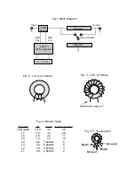
Page 3: ...nd scrape away the insulation from the end Don t solder them in until later Next wind T1 with 10 turns figure 5 It is the small black toroid and just under 1 2 inch in diameter The windings use the sm...

Page 4: ...C board Note that the mounting holes are offset slightly to help keep the inductors straight after installation The inductors can be pushed in until the windings touch the PC board Don t forget to scr...

Page 5: ...the 68HC11 can be placed into the socket and power applied Notice that U1 has a flattened corner that should match the socket Be careful here it will go in backwards and it will destroy the processor...

Page 6: ...match is found Note that while the processor is asleep the LEDs if used will also be disabled The processor can be woke up by pressing the tune button once while no RF is present It can also be force...

Page 7: ...ally tunes a lot of antennas to a lot of places A typical 40 meter dipole at 30 feet will tune anywhere from 2 1 to 30 MHz Average tuning time should be about 1 2 seconds An Antron 99 a 10 meter verti...

Page 8: ...If a transistor is found to be bad just about any 2N3904 type or equivalent will work The Relay number K1 K2 line up with transistor numbers Q1 Q2 This will help in matching a bad transistor to its re...

Page 9: ...e particular problem Upgrades We are continually trying to put more features in the software of the tuner The current version of the software QRP 1 0 was locked in with only 4 bytes out of 512 of code...

Page 10: ...bottom 2 bottom Inches needed 36 26 17 12 6 5 3 2 Fig 4 Inductor Table Fig 1 Block Diagram Inductors Capacitors SWR Sensor Hi Lo Z Switch Input Output 68HC11 Microprocessor User Interface REV Pwr FWD...

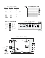
Page 11: ...able Layout 1 Cap Up 2 Ind Up 3 Cap Dn 4 Ind Dn 5 Green 6 Yellow 7 Red 1 8 Red 2 9 N C 10 Tune 11 N C 12 Auto 13 Gnd 14 Gnd Top Fig 9 Front Panel Wiring Inside View LEDs Tune Pin 10 Gnd Pin 13 14 Semi...

Page 12: ......

Page 13: ......

Page 14: ...1 R23 24 100K pots 2 C1 3 23 pf Trimmer 1 C3 8 10 13 17 19 24 36 52 0 01 uf 50V Mono 34 C9 10 uf 25V or 50V 1 C18 1 0 uf 25V or 50V 1 C15 16 25 27 10 pf 500V 5 C28 39 pf 500V 1 C29 82pf 500V 1 C2 C14...

Page 15: ......

Page 16: ......

Page 17: ......

Page 18: ......

Page 19: ......

Page 20: ......

Reviews: