


the SWR or tuning indicators in your installation, but they are there if desired.
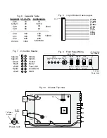
A ribbon cable is provided to make front panel connections (see figure 8 for wire assignments). Note
that when plugged in, the wire should extend away from the microprocessor. The two ground wires (pin 13 and
14) should be connected to the front panel ground wire (see figure 9).
The Auto/Semi input line is ground activated. That is, when the line is grounded, it will be in the Auto
mode. If it left floating, it in the semi mode. The Tune, Cap Up, Cap Dn, Ind Up, and Ind Dn are also ground
activated. Grounding the line will activate it. The LED current is supplied from the processor. The flattened
side (on the plastic part of the LED) should go to ground. You can see the flattened side by looking at the LED
with the leads facing you. The flattened side will be right next to one of the leads. See figure 9 for details on
wiring the front panel.
The typical minimum installation was envisioned to be just the Tune line run to a momentary contact
push button on the front panel of your transmitter. Nearly most of the time, the up / down buttons for the fine
tuning are not needed. The unit is set to find a match of less than 1.5:1 and nearly always does.
Once everything is mounted and wired, U1 (the 68HC11) can be placed into the socket and power
applied. Notice that U1 has a flattened corner that should match the socket. Be careful here, it
will go in
backwards and it
will destroy the processor if it is powered on while in the socket backwards. The writing on
the chip should be upside down while looking at the board while the inductors are on the top. On power up, the
unit will flash all LEDs (if used) once to indicate that everything has initialized successfully. Current draw
should be around 10 to 15 mA.
Each relay draws about 12 mA when energized. If a relay energizes on power up (a sign there is a
problem), you will not be able to tell (by current draw) if the processor is working properly. No relays
should energize when the unit is first powered on. The maximum current draw is about 190 mA with all the
relays energized. Since it is rare that all relays are energized, the average current draw is about 75 mA.
Alignment:
The tuner can be powered on or off during alignment. We recommend to leave it off so that
other components that could possibly have problems will not interfere. If you leave it on for testing, be sure to
place the Auto/Semi switch in the Semi position. Otherwise, it will start tuning while you are adjusting. Set
R23 and 24 to the center position. With a voltmeter on test point REV (marked on the silk screen) and about 5
to 10 watts applied to the input and a dummy load or resonant antenna on the output, tune C1 for minimum DC
4


