
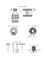


tuning capacitors, C25-34. Be sure to match the values from the capacitor chart (figure 6). The SIP resistor
pack can also be installed. Be sure to note the orientation of the SIP resistor (the tuner will not work if it is
installed backwards). A small line (or dot) on the side with writing marks pin 1.
Next install U2, the 34064 (use the parts placement sheet for orientation). Then U3, the 78L05. Next,
install Q1-17. Note the orientation. Then, the variable resistors R23 and 24. Then the Variable capacitor C1.
Now install T1. You may wish to use a small amount of silicon RTV or glue to hold T1 in place, but wait
until after the unit is tested before applying it in case there are problems. T1 will lay flat against the PC
board. The wire that carries the RF input from the transmitter will pass through the center of T1 and solder
directly to the PC board.
Now install the socket for U1. Note the orientation of the socket. The flattened corner goes in the lower
right, toward the crystal. There should also be an arrow inside the socket that will point away from the relays
(see the parts placement sheet). Do not install the 68HC11 until later. Then the crystal X1. Now, relays K1-
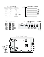
17 can be installed. Then the two electrolytic capacitors, C9 and 18, note the polarity.
Lastly, inductors L1-8 can be installed on the PC board. Note that the mounting holes are offset slightly
to help keep the inductors straight after installation. The inductors can be pushed in until the windings touch
the PC board. Don't forget to scrape the insulation off the ends before trying to solder. The #24 wire may be
stiff enough to support L5-8, but a non-acidic RTV or hot melt glue may be needed for L1-4 to hold them in
place. The RTV or hot melt glue should be used if you plan to use the unit in a mobile application.
Checkout:
The circuit should be "power on" tested once all the components except for U1 (the 68HC11
chip) have been installed. Apply 12 to 14 volts DC to the power input. Check for +5.0 volts on the output of the
78L05 (pin closest to U1). Current draw should be around 2.5 mA (anything less than 10.0 mA is acceptable).
If the volts and amps look good, you can proceed to mount the unit in a case or inside a transmitter and begin
wiring the user interface. Use the four mounting holes provided on the PC board, do not drill the mounting
holes on the PC board holes to make them larger.
J3 is laid out on the board as a 14 pin header with 0.1 inch spacing (figure 7). A header is provided for
wiring to the user interface. Depending on your particular installation, you may only want to connect a single
wire for the Tune button. If you desire the auto feature, you will have to either wire the Auto line to ground to
enable that mode or connect that line to a toggle switch to allow selection of modes. Likewise, you may not need
3


