background image


AT-200PC


Automatic PC-Controlled 

Antenna Tuner 

Manual Version 1.0


--- Preliminary ---


LDG Electronics 

1445 Parran Road, PO Box 48 

St. Leonard MD 20685-2903 USA 

Phone: 410-586-2177  

Fax: 410-586-8475 

[email protected] 

www.ldgelectronics.com


Summary of Contents for AT-200PC

Page 1: ...ic PC Controlled Antenna Tuner Manual Version 1 0 Preliminary LDG Electronics 1445 Parran Road PO Box 48 St Leonard MD 20685 2903 USA Phone 410 586 2177 Fax 410 586 8475 ldg ldgelectronics com www ldg...

Page 2: ...peration with provided LDG software 11 Software overview and setup 11 Software Operation 13 Operation with the N4PY Rig Control Software 16 Application Notes 18 When to use Auto mode 18 MARS CAP cover...

Page 3: ...ol LDG continues to define the state of the art in this field with innovative automatic tuners and related products for every amateur need Jumpstart or Real hams don t read manuals Ok but at least rea...

Page 4: ...Optional external Balun allows tuning of random length long wire or ladder line fed antennas Field upgradeable via software download Power requirements 11 to 16 volts DC at 750 mA max during tuning En...

Page 5: ...user interface The front panel has no controls or readouts All functions are controlled from a personal computer interface You can use any PC and operating system that supports a standard serial or U...

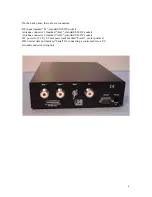
Page 6: ...ket Antenna connector 1 marked Ant 1 standard SO 239 socket Antenna connector 2 marked Ant 2 standard SO 239 socket DC power in 2 5 by 5 5 mm power jack marked Power center positive DB 9 serial data p...

Page 7: ...ound a common ground rod connected to buried radials is preferred but a single ground rod a cold water pipe can provide a serviceable ground LDG strongly recommends that you use a properly installed h...

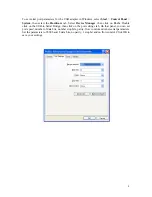
Page 8: ...anager then click on Ports Double click on the USB to Serial Bridge then click on the port settings tab On that panel you can set port speed number of data bits number stop bits parity flow control an...

Page 9: ...sceivers TenTec Orion Orion II Pegasus Jupiter Argonaut V Elecraft K2 See the N4PY web page at www n4py com for more details LDG provided software As a convenience LDG provides a simple control progra...

Page 10: ...ing transmission just start talking and your AT 200PC will match up in as little as 0 2 seconds Memory Tuning Your AT 200PC has frequency memories for four antennas on each antenna port They store the...

Page 11: ...is provided to you as is without warranty and LDG provides no support for it If you have problems or questions about the software LDG recommends you consult the LDG users group at http groups yahoo c...

Page 12: ...reaches the SWR you set The lower the SWR the longer it will take the tuner to reach a match A setting of 1 5 is usually a good compromise between tuning time and low SWR Updates On Off When set to o...

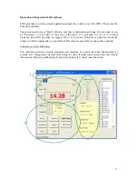
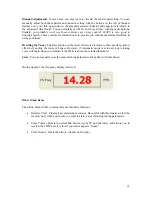
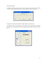
Page 13: ...in the upper left displaying the approximate frequency transmitted power level and achieved SWR Unkey your transmitter You can press Tune before transmitting if you wish the tune cycle will time out...

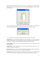
Page 14: ...n in the lower left resets all relays to their neutral position effectively putting the tuner in bypass However if Automatic mode is selected a new tuning cycle will begin when you transmit if the SWR...

Page 15: ...e and then click Ok You can also set the Hi Lo Z relay from this panel Set Capacitor Provides an alternate means to set the capacitor to a specific value Set Frequency Allows you to manually set the f...

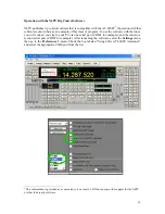
Page 16: ...ll connect your rig to your PC via one serial port COM1 for example and the tuner to a second serial port COM2 for example After launching the software select the Settings menu then go to the Preferen...

Page 17: ...adjusts the capacitor setting 5 Ind Manually adjusts the inductor setting 6 HiZ Manually toggles between Hi and Low Z setting 7 Sto Manually stores the present tuning settings 8 Rcl Tnr Initiates a me...

Page 18: ...S line must be asserted positive going for 3 milliseconds and then de asserted for 1 millisecond before sending each command this wakes up the tuner to receive the command Your AT 200PC is capable of...

Page 19: ...the High setting Set impedance range relay to Low Command code 9 Sets the Hi Low Z range relay to Low Select Antenna 1 Command code 10 Selects Antenna 1 on the internal antenna switch Select Antenna...

Page 20: ...Request forward power Command code 60 Requests tuner to report the forward RF power Request reflected power Command code 61 Requests tuner to report the reflected RF power Request SWR Command code 62...

Page 21: ...0 8 Sec Valid values of period range from 370 ticks 55 3 MHz to 11593 ticks 1 76 MHz A shortcut for determining the period value from the desired operating frequency in MHz is Period 20 480 Freq So fo...

Page 22: ...as 256 2 where is the factor in the classic SWR equation To calculate the SWR value from response code 06 simply divide the value in the second parameter by 256 take the square root of the quotient th...

Page 23: ...placed in standby mode In active mode Response code 14 Indicates that the tuner has restored the settings that were saved prior to entering standby mode Store OK Response code 15 Indicates that the r...

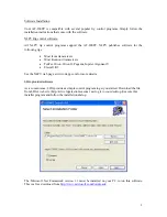
Page 24: ...folder and run the setup program Follow the installation instructions The default install file is c ldgelectronics Inc AT200OPCFirmwareDownloader 2 Download the update file these have a hex file type...

Page 25: ...n the code has been successfully loaded 9 Click OK to dismiss the Download Succeeded notice 10 Click Quit to exit the loader program 11 Power cycle the tuner by disconnecting then reconnecting DC powe...

Page 26: ...Touch no part inside the tuner while transmitting On reset the LEDs blink green red green In normal operation you should see this only at power up The green LED lights when the unit receives a serial...

Page 27: ...xhibit resistance and impedance in the form of capacitive or inductive reactance Transmitters transmission lines antennas and impedance The output circuit of your transmitter the transmission line and...

Page 28: ...sipated in the tuner as heat never reaching the antenna at all A tuner simply fools your transmitter into behaving as though the antenna were resonant avoiding any damage that might otherwise be cause...

Page 29: ...ce adjusted the forward and reverse power sensors produce a calibrated DC voltage proportional to the forward and reverse RF power levels These two voltages are read by the ADCs in the microprocessor...

Page 30: ...o watts is plenty Care and Maintenance Your AT 200PC tuner is essentially maintenance free just be sure to observe the power limits discussed in this manual The outer case may be cleaned as needed wit...

Page 31: ...e mail and bill you after repairs are completed Feedback If you have an idea to improve our software or hardware please send us a description If we incorporate your idea in the AT 200PC we ll send yo...

Reviews: