LCI Wyvern 2000N Handbook Download Page 4

2      Wyvern

®

 2000N Banknote Timer  Handbook
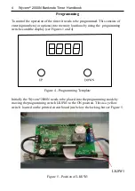
Installation

Mechanical Installation

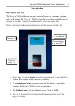
The Wyvern® 2000N timer should be mounted on a smooth vertical wall away

from corners so the cover lock can be easily accessed. The timer is 350 mm high
by 175 mm wide and has a depth of 140 mm so allow  sufficient clearance  for the
cover to swing down when opened. Take care to mount the case level in both the
vertical and horizontal axes; failure to do so may prevent correct operation of the
banknote acceptor. Choose an area where an ambient temperature of 40°C is not
exceeded, away from any source of moisture, dust or direct heat.

Open the case using the key supplied and position the case on the wall and mark

the position of the two upper keyhole slots. Plug the wall and fit two No. 8 or 10
screws of not less than 22 mm in length and hang the timer on these screws. Mark
the position of the lower two fixing screws and remove the timer and plug the wall.

Remove the required cable knockouts and fix the timer to the wall.

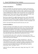
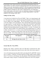
Electrical Installation

The timer will require a fused double pole switch for the mains input with a fuse

suitable for the load being controlled (maximum 5 amp). Using 20 mm conduit
with a male thread adaptor and lock ring, or a 20 mm nylon compression cable
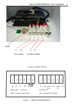
gland to provide strain relief , wire the unit as shown in Figures 2 and 3. Use
appropriately rated and approved cable relating to the relevant regional standards
up to a maximum current of 5 amp. Remove the safety shield before connecting
any wiring and replace safety shield after all connections are secured.

It is essential that the safety earth is connected to a known good earth. Unless
double insulated the load must be connected to the same bonding point as the main
earth to ensure good noise immunity.
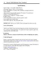
The Wyvern

®

 2000N is supplied as a voltage switching device - that is the

switched output is the same as the mains input voltage. In this case the load is
connected between pins 3 and 4. If a voltage free output is required (for example
to switch a device operating from a different supply) then the black link is
removed from between terminal block pins 5 and 6 and the load connected
between pins 3 and 5. See Figures 2 and 3.

NOTE. The Wyvern

®

 2000N accepts mains voltages in the range 110V - 240V

50/60 Hz.

Summary of Contents for Wyvern 2000N

Page 1: ...Handbook for the Wyvern 2000N Banknote Operated Timer Part Number 918 000 995 July 2012 Issue 3 ...

Page 2: ...ontrols International Ltd Clump Farm Industrial Estate Higher Shaftesbury Road BLANDFORD FORUM Dorset DT11 7TD United Kingdom Tel 44 o 1258 489075 455393 General or 44 0 1258 483577 483574 Technical support Fax 44 0 1258 488526 456410 E mail General enquiries info lci gb com Technical support support lci gb com Web www lci gb com 2008 2012 Wyvern is a registered trade mark of Leisure Controls Inte...

Page 3: ...play are used to program the Wyvern 2000N to user requirements 3 The banknote entry accepts banknotes upto 70mm in width 4 Access to the cash box is via the cover lock situated at the top of the Wyvern 2000N The Wyvern 2000N offers an extensive range of features to suit many banknote timer applications The Wyvern 2000N is supplied as a voltage switching device but may be used for voltage free appl...

Page 4: ...imer will require a fused double pole switch for the mains input with a fuse suitable for the load being controlled maximum 5 amp Using 20 mm conduit with a male thread adaptor and lock ring or a 20 mm nylon compression cable gland to provide strain relief wire the unit as shown in Figures 2 and 3 Use appropriately rated and approved cable relating to the relevant regional standards up to a maximu...

Page 5: ... Figure 2 Mains Wiring L N L N Mains Input Switched Output Earth 1 2 3 4 5 6 1 2 3 4 5 6 L N L N LINK L N LOAD N LOAD L OUT IN MAINS INPUT LOAD OUT MAINS INPUT MAINS VOLTAGE SWITCHING VOLTAGE FREE SWITCHING Figure 3 Output Switching Options ...

Page 6: ...locations by using the programming switches and the display see Figures 1 and 4 Figure 4 Programming Template Initially the Wyvern 2000N needs to be placed into the programming mode by moving the programming switch LKSW1 to the ON position This is a yellow switch located on the printed circuit board just below the locking bar see Figure 5 Figure 5 Position of LKSW1 LKSW1 ...

Page 7: ...til the last 2 digits flash when the UP and DOWN buttons can be used to set these digits to the required minutes The clock is set by holding both programming buttons for approximately 5 seconds The display then shows Hr and by using the UP or DOWN button can be toggled between 12 and 24 to allow selection of a 12 or 24 hour clock Hold both programming buttons for approximately 5 seconds to exit th...

Page 8: ...ribed earlier and using the UP and DOWN buttons move to option b Hold the UP button until the first digit flashes and the display shows b1 xx where xx is the value per note Using the UP and DOWN buttons select the CVPN program code required Hold the UP button down until the first two digits flash Use the UP and DOWN buttons to select the value required per note After approximately 10 second this v...

Page 9: ...elect the MSC value required After approximately 10 second this value is stored Start Delay time or Pre Time This is the time between inserting notes into the timer and the timer turning ON As soon as notes are inserted the display shows the time purchased but the load is not switched on for a time period determined by option 6 Once option 6 times out the load is switched on Setting option 6 to ze...

Page 10: ... UP button until the first digit flashes and the display shows 9 xx where xx is the lockout time Hold the UP button down until the first two digits flash Use the UP and DOWN buttons to select the lockout time required After approximately 10 second this value is stored Cool Down Time Option 8 allows a cool down time to be programmed This prevents notes being inserted until after a time lag has occu...

Page 11: ...een operated Total Audit Function 3 Audit function 3 displays the total number of minutes that the Wyvern 2000N has been active This includes total pre time and cool down time as well as count down time If pre time and cool down time options have been set to zero then audit functions 2 and 3 will be identical Currency Total Audit Function 4 Audit function 4 is selected with audit code c and shows ...

Page 12: ...rror messages will show for 10 seconds on the display before returning to the current task however if the cashbox was detected as full or jammed then the display will show Err4 for 1 second every 5 seconds no matter what task is occurring until it is cleared this by viewing option c While the cashbox is jammed or full the note reader will be inoperative and about every 5 minutes will try to stack ...

Page 13: ...nt before timing starts 7 6 Pre time Set to zero if not required 7 8 71 79 STPN Session time per note Set to 00 if not required 5 6 8 Cool down after session time Set to 00 if not required 8 9 Lockout max session time Set to 00 if not required 8 A Not used N A b1 b9 CVPN Currency value per note Set to 00 if not required 6 7 d Real time 12 or 24 hour clock Set to 00 00 to turn clock off 5 ...

Page 14: ...f Interrogation Codes Selection Code Description Page Maximum 1 Total sessions activated 12 65535 2 Total hours load has been on 12 65535 3 Total hours used including pre and cool down time 12 65535 c Total currency value for accepted notes 12 999999 ...

Page 15: ...r indoor use only Service Information The Wyvern 2000N Timer has been designed to provide reliable long term use for a variety of timing applications No regular servicing is required apart from emptying of the note stacker unit WARNING Remove all sources of power from the timer before attempting any repairs Technical Support Before contacting technical support visit the FAQ section of Leisure Cont...

Page 16: ... 2008 2012 Leisure Controls International Ltd ...

Reviews: