background image


Tutorial 

44/ 68 

V1.3/0 

2.

Using the trackball or navigation buttons focus on the list 
of productions in the lower part of the display. 

The four soft key functions update to show LOAD, NEW and 
SAVE. 

3.

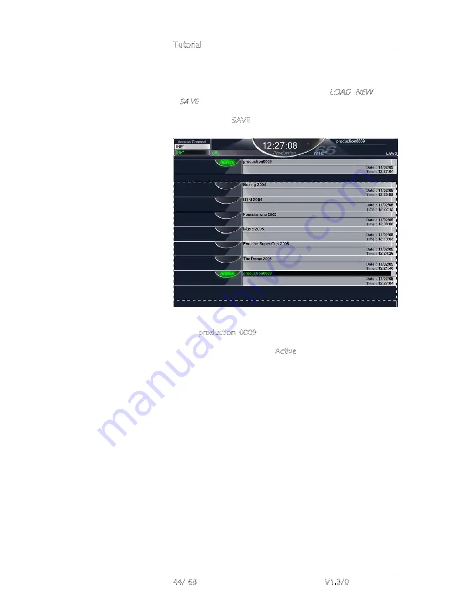
Press the SAVE soft key to save the current console 
settings into a new production: 

A new entry appears in the productions list with a default name 
(e.g.  production  0009).  This  entry  contains  all  the  settings  of 
the console and is time and date stamped. The new production 
automatically  becomes  the  Active  production  as  shown  on  the 
display. 

Summary of Contents for mc266

Page 1: ...mc 66 Tutorial Version V1 3 0 Edition 05 12 14...

Page 2: ...ers It cannot be guaranteed that all product names products trademarks requisitions regulations guidelines specifications and norms are free from trade mark rights of third parties All entries in this...

Page 3: ......

Page 4: ...1 Entering Names from the Keyboard 26 Getting Started 27 Switching on the Power 27 Loading a Setup Production 28 Interrogating the Channel Fader Strips 30 Switching Banks and Layers 30 Creating Your O...

Page 5: ...55 Activating the Mix Minus Sends 58 Using VCA Grouping 59 Assigning VCA Masters to the Control Surface 59 Assigning Channels to a VCA Master 60 Applying Signal Processing 61 Using the 4 band Equalis...

Page 6: ...Table of Contents mc 66 V1 3 0 7 68...

Page 7: ...d the index directory are provided at the end of the manual Conventions Throughout this manual we will be using a number of conventions Headings Every new topic is clearly identified in large bold fon...

Page 8: ...ERCASE and button cap engravings are written in bold for example press the INPUT button located on the ACCESS CHANNEL ASSIGN control panel in the centre section of the console On screen buttons which...

Page 9: ......

Page 10: ...s free controls offer additional local channel control A fifth upper controller is dedicated for input gain In addition every 8 fader channel section houses a high resolution TFT display providing fee...

Page 11: ...eeds Configurations may be changed at any time making it easy to modify the mix structure if you decide for example that the production requires some additional groups The choice of DSP configuration...

Page 12: ...f the six banks each fader strip has two layers Layer 1 and Layer 2 Layers can be switched either globally or individually making them ideal for fast access to related sources For example assign a mai...

Page 13: ...any output mix routed to any destination In addition you may route sources directly to destinations for example to feed a Mic Line input to an AES output for archive recording purposes Perhaps the mos...

Page 14: ...al user data flashcard Within each production folders may be created to store snapshots and sequences Snapshots provide the ability to store different mixes setups for recall before or during the show...

Page 15: ...th timecode rolling forwards backwards and at any speed providing fast and efficient mixing The way in which data is written is governed by a number of modes allowing you to write dynamic or static au...

Page 16: ...ignments In each case the philosophy of operation is to place a channel in access and then assign it directly to a destination This provides fast configuration of the console without navigating throug...

Page 17: ...SSIGN button changes the operation of the panel from access to assign The ESC button which can be used to exit any operation Navigation buttons LEFT RIGHT NEXT and PREV The ENTER button for confirmati...

Page 18: ...ck busses up to 96 SUM Sum masters up to 48 VCA VCA masters up to 16 MAIN FADER selects the channel type as assigned to one of the 8 main fader strips STRIP selects the channel type as assigned to one...

Page 19: ...to channel fader strip 8 pressing the LEFT button selects the DSP channel assigned to fader strip 7 The name and label for your selected channel are shown in the CHANNEL and LABEL displays Note that...

Page 20: ...each with its own alphanumeric display The trackball with left and right blank select buttons One of the displays is always active on the central control screen and some buttons such as SIGNAL cycle t...

Page 21: ...d to create and run real time sequence automation Edit Sequence for offline editing of sequences 7 Press METER to view the four pages of assignable meters within the Metering display 8 Press PROD FILE...

Page 22: ...he soft key functions located above the trackball in order to perform different operations Text within grey boxes may be selected to provide further options for example selecting Digital updates the S...

Page 23: ...e the navigation buttons as follows Press the DEC Left or INC Right buttons to focus on an area of the display for example Source Name and Label The focussed area is shown by the dotted black and whit...

Page 24: ...LOAD SAVE and UPDT functions as indicated in the alphanumeric displays 2 Select the Signals display by pressing the SIGNAL button The soft keys update to provide CONN and DCON functions 3 And so on fo...

Page 25: ...ighlighted in black 2 Select the PAGE button located in the middle of the SCREEN CONTROL soft keys The four soft keys update to PROT EDIT and DEL 3 To rename the snapshot press EDIT A green cursor app...

Page 26: ...in a generic setup production which will provide an excellent starting point for new templates you wish to create Switching on the Power The mc2 66 consists of three principal system components Consol...

Page 27: ...torage and store all the settings required for a production or type of job Depending on the installation you may have a number of setup productions or only one Each should be clearly labelled for exam...

Page 28: ...ll the productions stored on the internal user data flash card 2 Select the production you wish to load from the lower part of the display using the trackball or navigation controls for example Olympi...

Page 29: ...strips In our example input channel 1 is assigned to the active layer INP1 with nothing assigned to the alternate layer The two black boxes display the programmable user labels for these channels In o...

Page 30: ...the FLIP button to invert the layer for all fader strips channel and main This inverts the current layer selections allowing you to view all hidden channels on the alternate layer with one button push...

Page 31: ...the purposes of this tutorial we are going to assume that you have a DSP configuration with some input channels groups sums and auxes We are also going to assign our channels to the control surface b...

Page 32: ...fader SEL buttons flash in green to indicate possible destinations for your selected channel 3 Press the fader SEL button on main fader strip 8 to complete the assignment The fader SEL button stops fl...

Page 33: ...the name and label for input channel 1 2 Select the FIRST LAST button located on the STRIP ASSIGNMENT ASSIGN MODES panel 3 Press the fader SEL button on channel fader strip 1 followed by the fader SEL...

Page 34: ...ed to AES inputs 01 and 02 2 Using the trackball or navigation buttons select the source directory e g Digital and sub directory e g HD AES IN 1 24 on the left of the display Your selections are highl...

Page 35: ...ween AES301 and INP23 Look at fader strip 23 on the control surface the fader strip and Channel display name and labels update and hopefully you are metering some audio 6 Repeat steps 3 to 5 to route...

Page 36: ...e BUS ASSIGNMENT REVERSE panel The INPUT button flashes and across the console the fader SEL buttons on fader strips which are controlling input channels INP 1 24 flash in green to indicate possible s...

Page 37: ...4 pre programmed buttons to select SUM 1 as your monitor source 2 Use the CRM 1 rotary control to set the main monitor level 3 Press the ALT button to switch the CRM 1 output to an alternate set of sp...

Page 38: ...Control Room Monitoring panel to clear all current AFL and PFL selections Note that depending on your monitoring configuration AFL and PFL signals may appear on the Control Room 1 Control Room 2 or e...

Page 39: ...ry e g Stagebox and sub directory e g Mics on the left of the display Your selections are highlighted in black and the Source Name and Label columns update to show all available sources 3 Now select e...

Page 40: ...with a green line showing the route between Mic_06 1 and Inp 1 In addition the source and destination selections automatically step down to the next entries in the list 8 Continue pressing the CONN bu...

Page 41: ...y set the microphone preamplifier gain The gain range is normally adjusted from 0dB to 70dB although this may vary depending on your hardware configuration Please refer to the DALLIS I O technical dat...

Page 42: ...plates or for a particular show Note that within each production you may create folders to store snapshots Snapshots store high level settings and provide the ability to store different mixes setups w...

Page 43: ...e to show LOAD NEW and SAVE 3 Press the SAVE soft key to save the current console settings into a new production A new entry appears in the productions list with a default name e g production 0009 Thi...

Page 44: ...r appears highlighting the first letter of the existing name in this case the letter p 4 Edit the name by typing a new name on the keyboard Note that as you type you overwrite the existing name Theref...

Page 45: ...on To update a production 1 Select the production by focussing on its name either using the trackball or navigation buttons Note that the Active production production0009 is selected by default 2 Pres...

Page 46: ...they are assigned to the control surface in exactly the same way we assigned our input and sum channels Repeat the fader strip assignment operation described on Page 32 to assign GROUPS 1 to 4 onto m...

Page 47: ...tons on the fader strips controlling INP 1 to INP 8 to undo the bus assignments The fader SEL buttons change colour from red to green and the Channel display indicates the updated bus assignments 4 Wi...

Page 48: ...ss the console the fader SEL buttons on fader strips which are controlling input channels INP 1 24 flash in green to indicate possible sources for the chosen destination 3 Press the fader SEL buttons...

Page 49: ...tor GRP 1 if available 2 Press the AFL button located on the fader strip controlling GRP 1 to listen to the group output post fader 3 Press the PFL button located on the fader strip controlling GRP 1...

Page 50: ...ction The CHANNEL and LABEL displays update to show the system name and label for SUM 1 2 Locate the IMAGE controls on the Central Control Section 3 Press the STE button This links SUM 1 to its adjace...

Page 51: ...r destination 1 Press the SIGNAL button located on the SCREEN CONTROL panel to view the Signals display 2 Using the trackball or navigation buttons select the source directory e g Bus Out and sub dire...

Page 52: ...bove the trackball The Signals display updates with a green line showing the route between SUM1 and AES3_001 6 Repeat steps 3 to 5 to route the right hand side of the stereo sum master SUM2 to AES3_00...

Page 53: ...LABEL displays and the Central Control Section panels update to show the current settings for the sum master 2 Locate the AUXILIARY AUDIO FOLLOWS VIDEO controls on the Central Control Section 3 Press...

Page 54: ...xiliary Sends The first step is to configure the auxiliary sends to be used for each mix minus feed This is done from the signal Settings display by linking the auxiliary you wish to use to the input...

Page 55: ...and destination settings We are interested in the Mix minus box at the bottom left of the display 4 Select the Mix minus box either using the trackball or navigation buttons and use the rotary contro...

Page 56: ...source directory e g BUS Out sub directory e g DirOut AUX X 1 16 and Name or Label for the source you wish to route e g AX 1 Your selected source is highlighted in black 9 Next select the destination...

Page 57: ...u may wish to send the output of several replay machines to all the mix minus recipients The channels are routed onto the mix minus bus therefore feed all mix minus sends The CORD button changes the m...

Page 58: ...e active surface by pressing the MAIN 2ND button located on the LAYER access panel 2 Now select VCA master 1 from the ACCESS CHANNEL ASSIGN control panel by pressing VCA the number 1 and the Enter but...

Page 59: ...o indicate that it is active and across the console the fader SEL buttons flash in green to indicate possible sources for your chosen master 3 Now press the SEL buttons on the fader strips controlling...

Page 60: ...trip to assign it to the Central Control Section The controls update to show the current settings for the assigned channel When controlling processing note that all rotary controls on the mc2 66 are t...

Page 61: ...l As you adjust controls the display updates to reflect your settings Note that the name and label for the channel you are adjusting is always shown at the top left of the display Also note that the h...

Page 62: ...frequency or Q for each of the 4 bands Frequency may be set from 20Hz to 20kHz and the value is shown beneath the front panel control and in the FREQ box on the Main display Gain may be set from 24dB...

Page 63: ...Hi P or Lo P respectively 4 Use the FREQ rotary control to set the roll off frequency for the filter Frequency may be set from 20Hz to 20kHz and the value is shown beneath the front panel control and...

Page 64: ...d button and use the two upper controls to set the release time ATT RLS and look ahead delay The front panel displays and boxes on the Main display update to show the relevant settings The action of t...

Page 65: ...mount of delay is displayed in the TIME box on the Main display Channel delay may be set from 0 to 1800ms or 612m or 45 frames Inserting Outboard Processing To insert an outboard piece of equipment in...

Page 66: ...1 24 and source e g INP1i on the left of the display Your selected source is highlighted in black 3 Next select the destination in a similar fashion For example select Stagebox as your directory Anal...

Page 67: ...8 V1 3 0 5 Repeat steps 2 to 4 to route the line input from the compressor e g ANA13 1 to the insert return INP1i The Signals display updates with a green line showing the route between the source and...

Page 68: ...ed to the left of the Central Control Section 1 Check that the Page 2 button is turned off 2 Press the EQ 1 FI 1 button Working up the channel the four free controls are now assigned to On Off Gain Fr...

Reviews: