


Superabrasive
User
Manual
Original
Language
Lavina®
25LM
‐
S
‐
E
12/2014
13
8.
MAINTENANCE
AND
INSPECTION
CLEANING
Keep
your
machine
clean.
Cleaning
the
machine
on
a
regular
basis
will
help
detect
and
solve
potential
problems
before
they
can
cause
damage
to
the
machine.
Most
importantly,
check
and
clean
the
tool
plate
connections,
power
cord
and
plugs,
vacuum
hoses,
and
water
tank.
CHECK
DAILY
After
operating
the
Lavina
S
machine,
the
operator
should
conduct
a
visual
inspection
of
the
machine.
Any
defect
should
be
solved
immediately.
Pay
attention
to
power
cords,
plugs
and
vacuum
hoses,
loose
bolts
or
screws.
Tool
holders:
Buffers
and
spiders
are
consumables
and
must
be
visually
checked
every
day
and
replaced
when
needed.
Make
sure
flanges
and
discs
are
mounted
and
locked
well
in
place.
The
key
lock
holders
(butterflies)
should
be
checked
also.
Check
the
rubber
buffers
and
the
fixing
of
the
holdings.
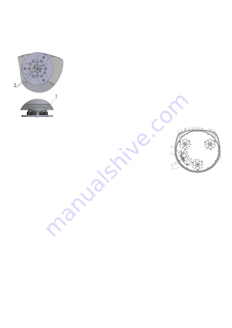
The
flange
holding
the
buffers
(Fig8.1
1)
has
to
be
firmly
fixed
to
the
unit.
A
gap
seen
there
means
that
there
are
loose
screws
securing
the
holder.
The
screws
have
to
be
tightened
immediately
to
safely
operate
the
machine.
Working
with
loose
screws
on
the
holder
could
also
cause
damage
to
the
machine.
The
tightening
force
of
the
screws
has
to
be
25…
30N.m
(18…22
ft/lbs).
It
is
very
important
to
regularly
check
the
screws
(Fig.8.1
2)
that
fix
the
“QuickChange”
holder
to
the
safety
part,
so
that
the
holder
will
not
fly
away
if
the
buffers
get
damaged.
The
tension
of
the
planetary
belt
can
be
checked
daily
by
moving
the
head
and
feeling
the
resistance
of
the
moving
pulleys,
if
the
belt
slips
tension
immediately,
see
the
chapter:
Troubleshooting.
CHECK
AND
REPLACE
AFTER
THE
FIRST
15
WORKING
HOURS
Check
the
belt
tension
after
15
hours
of
working
with
the
machine.
The
bottom
cover
has
a
control
cover
(Fig.8.2)
that
allows
for
fast
and
easy
control
and
correction
of
the
belt.
It
is
recommended
that
the
tension
of
the
belt
be
tested
after
the
first
15
hours,
and
tightened
if
necessary.
For
the
correct
tension,
see
the
chapter:
TROUBLESHOOTING
“mounting
the
belt”.
Every
time
you
open
the
control
cover,
mount
all
the
screws
back
with
washers.
CHECK
EVERY
200
WORKING
HOURS
Every
200
working
hours,
the
operator
should
inspect
all
parts
of
the
machine
carefully.
Most
importantly,
inspect
and
clean
the
tool
plate
connections,
power
cords
and
plugs,
vacuum
hoses
and
the
water
tank
filter.
Also,
check
the
water
flow
of
the
pump.
Check
the
guard
assembly.
Make
certain
that
the
wheels
are
clean
and
are
rotating
properly.
Inspect
the
control
buttons.
If
there
are
defective
control
parts,
they
should
be
replaced
immediately.
Replace
worn
vacuum
and
water
hoses.
Check
the
tension
of
the
belt
and
tighten
it
when
necessary.
For
the
correct
tension
see
the
chapter,
TROUBLESHOOTING.
Dismount
the
tool
holders
(see
TROUBLESHOOTING)
replace
all
parts
(spider,
buffers,
sealer
caps,
“O”
rings)
with
the
slightest
damage.
Open
the
inspection
cover
on
the
motor
base
to
check
on
the
planetary
driving
belt;
by
moving
the
main
head,
the
belt
should
not
slip
on
the
planetary
pulley
and
drive
the
pulleys.
CHECK
EVERY
400
WORKING
HOURS
Besides
the
checks
of
200
working
hours,
replace
the
sealer
and
V
‐
rings
like
described
in
the
chapter:
TROUBLESHOOTING,
replacing
belt
and
pulley
units.
Check
is
the
belts
and
bearings
are
in
good
condition,
change
if
needed.
VACUUM
As
previously
stated,
frequently
check
hoses
and
other
parts
for
clogging.
WATER
LEAKS
Replace
any
leaking
parts
immediately
as
the
water
could
damage
your
machine.
MECHANICAL
PARTS
Parts
such
as
the
belts,
seal
rings,
spiders
and
buffers,
and
guard
assembly
are
subject
to
wear
and
should
be
replaced
as
needed.
ELECTRICAL
SYSTEM
Dust
should
not
enter
the
control
box,
as
it
will
destroy
the
contacts.
Remove
(blow
out)
any
dust
present.
Figure 8.2
Figure 8.1


