background image


G. 

It will be easier to outside clamp the wheel to the 

table top if the long side of the rim is loosened last. 
 
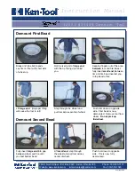
4.  Apply  tire  manufacturer’s  approved  rubber  lubricant 
liberally  to  entire  circumference  of  both  tire  beads  after 
loosening (figure 5).


5. Determine the mounting side of the wheel. The mounting 
side is the narrow side of the drop center. See figure 2 for 
more information on the drop center. 
 
6.  Place  tire/wheel  assembly  on  table  top  with  mounting 
side up (figure 6). Use the clamp control pedal to move the 
clamps inward (push pedal down) or outward (toggle pedal 
up). Clamp steel wheels from the inside (clamps push out-
ward against wheel). Clamp mag and custom wheels from 
the  outside  (clamps  push  inward  against  the  outside  rim 
edge). Refer to the Custom and Special Wheels section.


7. Move the swing arm into position. Pull the locking handle 
forward  to  release  the  slide.  Push  down  on  the  top  of  the 
vertical slide to move the demount head into contact with the 
rim edge. Push the locking handle back and lock the slide into 
place (figure 7).


Figure  7  -  Position 
Mount/Demount 
Tool


8. The mount/demount head should be in contact with the rim 
edge. Turn the swing arm adjusting knob to move the mount 
demount head away from the rim 1/8 to 1/4 inch (figure 8).


9.  Check  metal  head  positioning.  Mount/demount  metal 
head should be positioned with 3/16 to 1/8 inch clearance 
between the top of the rim edge and the bottom of the head, 
and 1/8 to 1/4 inch clearance between the rim edge and the 
head roller. This clearance will be maintained as long as the 
locking handle and adjustment knob are not changed. The 
operator may swing the arm out of the way and back into 
place again without needing to reposition the head (when 
changing a like set of wheels) (figure 9).


Figure 4 - Position Tire and Bead Loosener Shoe With Wheel 
Turned Around 

Figure 5 - Apply Rubber Lubricant to Tire Beads


Figure 6 - Place Tire/Wheel Assembly on Table top 

Figure 9 - Proper (Metal) Mount/Demount Head Position 

Summary of Contents for TWC-401NIC

Page 1: ...ation of the machine such as safety warning and precautions assembly operating main tenance and parts list as sembly diagrams Keep your invoice with this manual for future reference Manufacturer shall...

Page 2: ...x77x100cm Shipping Weight 220kg 230kg Voltage 0 9 1 1 of nominal voltage Frequency 0 98 1 02 of nominal frequency Ambient Temperature 5 40 C Operation Humidity 30 95 Installation altitude NOT exceed 1...

Page 3: ...r Pedal 2 Jaw clamp Pedal 3 Reverse Pedal 4 Turntable 5 Jaw 6 Mounting head 7 Hexagonal shaft 8 Swing arm 9 Locking handle 10 Column 11 FRL 12 Shovel 13 Rubber wheel support 14 STL 1 2 3 4 5 6 8 10 11...

Page 4: ...4 1 Optional Upgrade Accessories...

Page 5: ...ker 3 Connect the inflation gun if it is to be installed to its connector 4 Connect the tire changer to a compressed air network Suggested working pressure is 8 bar using the connector which is on the...

Page 6: ...ion against the bumper pads and excessive wear on pivots Deflate the tire completely to prolong the life of your machine 1 Deflate the tire completely by removing the valve core from the valve stem fi...

Page 7: ...the top of the vertical slide to move the demount head into contact with the rim edge Push the locking handle back and lock the slide into place figure 7 Figure 7 Position Mount Demount Tool 8 The mo...

Page 8: ...r bead lift Figure 10 Insert Bead Lifting Tool 11 Push the bead lifting tool down towards the wheel to lift the tire bead up and over the knob portion of the demount head Hold the tool and bead in thi...

Page 9: ...without checking both tire and wheel for damage and to be certain the sizes match Do not let untrained persons operate tire changer and keep bystanders out of service area Forcing the tire onto the r...

Page 10: ...tube type tires mount lower bead first move swing arm out install tube and then mount upper bead 9 Inflation Tire inflation is performed in three steps BEAD SEAL BEAD SEAT and INFLATION These steps ar...

Page 11: ...nd debris to be blown into the air with enough force to injure operator and or bystander Do not use the bead sealing control position to inflate a tire S This unit is equipped with a pressure limiter...

Page 12: ...ating will usually require at least 7 PSI in the tire 40 PSI is the maximum safe pressure at this stage regardless of tire operating pressure Most European import cars and many aftermarket alloy wheel...

Reviews: