


DAYTONA PRODUCTS | A DIVISION OF BUDGET AUTOMOTIVE EQUIPMENT
101 APPLEWOOD DR. | BRIGHTON, ON K0K 1H0 | 1.866.219.9991
WWW.DAYTONAPRODUCTS.COM
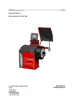
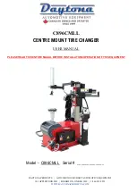
C896CMLL
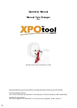
CENTRE MOUNT TIRE CHANGER
USER MANUAL
PLEASE READ THIS ENTIRE MAUAL BEFORE INSTALLATION/OPERATION OF THIS EQUIPMENT
Model - C896CMLL Serial # _____________
Summary of Contents for C896CMLL
Page 20: ...7 0 Explosive View ...