Lastolite lumen 8 User Manual Download Page 10

The F200/400 fuse protects the unit from further damage after a component malfunction. In many

cases, the cause of a fuse blowing may simply be a modelling lamp failure. Some lamps temporarily

short-circuit when they fail causing the unit's fuse to blow; there may then be no other malfunction in

the unit. Once the fuse and lamp has been replaced, the unit can be ready to use once again.

If the fuse has blown, both the illuminated Power on/off switch and the Ready indicator will not light

when power is applied to the unit.

Note: 

It is important to replace the fuse only with one of the same rating. For both units, the fuse type

is as follows: 

6Amp (or 6.3Amp), 20mm, 220-250V, Antisurge, Ceramic.

The fuse designation is sometimes written as: 6.3A(T) or 6.3AL

For convenience, all flash units are provided with a spare fuse built into the fuse-holder.

The following procedure must be taken to replace the fuse:

11

Fuse Replacement

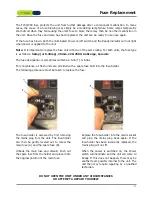
The fuse-holder is accessed by first removing

the mains plug from the unit. The fuse-holder

can then be gently levered out to reveal the

main fuse (A) and the spare fuse (B).

Unhook the main fuse and discard. Push out

the spare fuse from the holder and place it into

the original position of the main fuse. 

Replace the fuse-holder into the mains socket

and plug the mains plug back again. If the

fuse-holder has been incorrectly replaced, the

mains plug will not fit.

When the power is switched on, the Power

switch will illuminate and the unit will come to

Ready. If this does not happen, there may be

another fault, possibly internal to the unit. The

unit then may require repairing by a qualified

technician.  

DO NOT OPEN THE UNIT UNDER ANY CIRCUMSTANCES

OR ATTEMPT A REPAIR YOURSELF

Summary of Contents for lumen 8

Page 1: ...User Manual...

Page 2: ...ctor 2 Reflector Release Button 3 Slave Cell 4 Lighting Stand Clamp 5 Clamp Screw 6 Umbrella Clamp Screw 7 Umbrella Clamp 8 Reflector Umbrella Slot 9 Inner Reflector 10 Flash Tube 11 Reflector Bayonet...

Page 3: ...Power Socket 14 Fuseholder Fuses 15 Power On Off 16 Modelling Lamp On 17 Modelling Lamp Full 18 Slave Cell On 19 Beeper Sounder On 20 Flash Test Button 21 Ready to Fire Indicator 22 Flash Modelling P...

Page 4: ...th one hand while adjusting the tilt with the other OPERATING PRECAUTIONS SAFETY The F200 400 units are designed for indoor use only and for connection to domestic 220 240VAC single phase only The uni...

Page 5: ...sory if it is possible Line up the reflector bayonets over the slots as shown If an umbrella reflector is also going to be used orientate the reflector so that the oblong reflector slot is at the bott...

Page 6: ...are when fitting a lamp 11 The ES screw socket may require the lamp to be fully screwed down in order to make contact If a new lamp fails to light check that it is fully screwed down 12 Take care not...

Page 7: ...his function the photographer can easily check from the camera position that all units have flashed When the Full switch is switched up the modelling lamp function changes the lamp will stay on when t...

Page 8: ...ll increase the flash by another one stop approximately double the light Mid way positions can be used for increases in light of less than one stop the control has small click indents to aid fractiona...

Page 9: ...be flashed Do not try to fire the unit before this indicator is lit When firing the unit at short intervals refer to the maximum advisable flash rate firing the unit too quickly can cause the flash tu...

Page 10: ...3AL For convenience all flash units are provided with a spare fuse built into the fuse holder The following procedure must be taken to replace the fuse 11 Fuse Replacement The fuse holder is accessed...

Page 11: ...amp Modes Full Prop Off Full Prop Off Auto Dump Yes Yes Colour Temperature 5300 5600k 5300 5600k Slave Cell Yes 10 metres Yes 10 metres Triggering Methods Sync Test Slave Sync Test Slave Main Operatin...

Reviews: