63
6. ELECTRONIC CONTROL INSTRUCTIONS
6-2-2. FUNCTION TABLE
NO
Function
Controlled
Part
Description
1
Initial
Operation
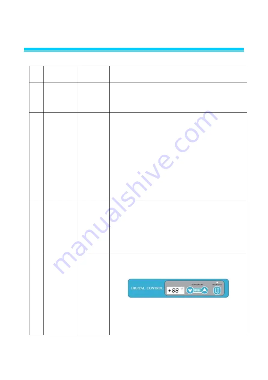
1. LED displays inside temperature.
2. Begins to run immediately if higher than 41℉ and
begin to run after 5 minutes pause if lower than 41℉.
2
Temperature
Control
Compressor
LED
1. The Temperature can be changed by pushing up/down
buttons.
2. LED displays inside temperature
3. Buzzer buzzes 1 time whenever a button is pressed
4. Compressor automatically turns on and off by C-sensor
(Except error mode)
5. Comp. On/off temperature at C-sensor(℉)
Setting 39 38 37 36 35
Comp On
42 41 40 39 38
Comp Off
36 35 34 33 32
Setting
34 32 30 28
Comp On 37 35 34 32
Comp Off 31 29 28 26
3
Error
Display
LED
1) Press `up' button 3 times while pressing and holding
`down´ button.
Above procedure switches normal display to error
display mode. And then 88 LED indicates, `(D1)' or
`(C1)' respectively.
2) 10 seconds after the last button pressed, error display
mode will be switched to normal display mode.
4
Defrost
Function
Compressor
1) Defrost can be set by pushing the button for 3
seconds. (3h, 6h, 9h, 10h(ah) )
2) While the compressor runs for over 3 hours, defrost
system will
automatically be driven without any additional control
order.
Summary of Contents for LRB-771PC
Page 1: ...1 Commercial Upright Refrigerator Freezer Service Manual...
Page 4: ...4 1 ASSEMBLY LRB 771PC...
Page 6: ...6 1 ASSEMBLY LFB 771PC...
Page 8: ...8 1 ASSEMBLY LRB 771PCG...
Page 10: ...10 1 ASSEMBLY LRB 1471PC...
Page 12: ...12 1 ASSEMBLY LFB 1471PC...
Page 14: ...14 1 ASSEMBLY LRB 1471PCG...
Page 38: ...38 3 WIRING DIAGRAM 3 1 REFRIGERATOR LRB 771PC LRB 1471PC...
Page 39: ...39 3 WIRING DIAGRAM 3 1 REFRIGERATOR LRB 771PCG LRB 1471PCG...
Page 40: ...40 3 WIRING DIAGRAM 3 2 FREEZER LFB 771PC LFB 1471PC...
Page 41: ...41 4 PART DETAILS 4 1 TOP PANEL Display PCB Main PCB...


