background image

60 


6. ELECTRONIC CONTROL INSTRUCTIONS


  6-1-2. FUNCTION TABLE &  MANUAL DEFROST 

NO


Function


Controlled 


Part


Description


1


Initial


Operation


1. LED displays inside  temperature.


2. Begins to run immediately if higher than 50℉  and


      begins to run after 5 minutes pause if lower


      than 50℉.


2


Temperature


Control


Compressor


LED


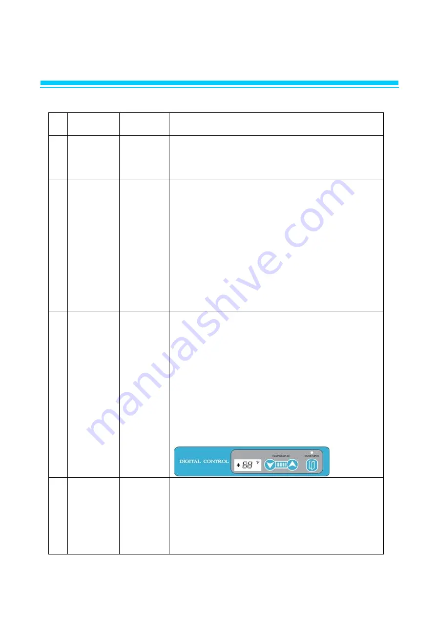
1. The Temperature can be changed by pushing up/down


      buttons.


2. LED displays inside temperature


3. Buzzer buzzes 1 time whenever a button is pressed


4. Compressor automatically turns on and off by C-sensor


      (Except error mode)


5. Comp. On/off temperature at C-sensor (℉)


      Setting5.03.01.0-1.0-2.0


      Comp On86321


      Comp Off20-3-4-5


      Setting-3.0-5.0-7.0-9.0


      Comp On0-2-4-6


      Comp Off-6-7-9-10.5


3


Defrost


Function


Heater


Compressor


1) Defrost function is controlled time interval setting.


2) Factory setting is every 8 hours. 


3)  If it becomes defrost cycle time, Defrost heater is 


      operated when D-sensor senses below 23℉.


4)  Defrost heater terminates when D-sensor temperature 


      comes  to above 53℉, then compressor will start after 


      10 minutes.


5) During defrost period, LED displays dF.


6) If D-sensor does  not cut off defrost heater, main pcb 


      has a back up for defrost time, the maximum is 


      40 minutes.


7) Defrost can be set by pushing the button for 3 seconds. 


(3h, 6h, 9h, 10h(ah) )


4


Error


Display


LED


1) Press `up' button 3 times while  pressing and holding 


    `down´  button.


      Above procedure switches normal display to error


      display mode. And then 88 LED indicates, `(D1)' or 
`(F3)'


      or `(C1)' respectively.


2) 10 seconds after the last button pressed, error display 


      mode will be switched to normal display mode.


Summary of Contents for LRB-771PC

Page 1: ...1 Commercial Upright Refrigerator Freezer Service Manual...

Page 2: ...OF CONTENS 1 ASSEMBLY 4 15 2 PARTS 16 37 3 WIRING DIAGRAM 38 40 4 PART DETAILS 41 45 5 MAIN COMPONENTS 46 58 6 ELECTRONIC CONTROL INSTRUCTIONS 49 64 7 REPLACEMENT OF MAIN COMPONENTS 65 81 8 PART LIST...

Page 3: ...ts danger of fire such as TRACKING SHORT Check whether water has gone into the electric parts When there are traces of water exchange the parts or enact the TRACKING prevention device After repairing...

Page 4: ...4 1 ASSEMBLY LRB 771PC...

Page 5: ...INGE BOTTOM ZDC 2 T10 42 63 1 18 R3393 530 LOW SHAFT RH 24 31 1 19 R3813 351 COVER CAPACITOR GI T0 8 255 2 135 1 20 R3853 110 EVAPORATOR AIR GUIDE LF AL WHITE T0 5 162 247 1 21 R3853 390 EVAPORATOR AI...

Page 6: ...6 1 ASSEMBLY LFB 771PC...

Page 7: ...R3813 351 COVER CAPACITOR GI T0 8 255 2 135 1 20 R3853 110 EVAPORATOR AIR GUIDE LF STS443CT 2B T0 5 161 8 269 1 21 R3853 390 EVAPORATOR AIR GUIDE REAR STS430 2B T0 5 125 155 1 22 R3853 090 EVAPORATOR...

Page 8: ...8 1 ASSEMBLY LRB 771PCG...

Page 9: ...FT RH 24 31 1 19 R3813 351 COVER CAPACITOR GI T0 8 255 2 135 1 20 R3853 110 EVAPORATOR AIR GUIDE LF STS443CT 2B T0 5 161 8 269 1 21 R3853 390 EVAPORATOR AIR GUIDE REAR STS430 2B T0 5 125 155 1 22 R385...

Page 10: ...10 1 ASSEMBLY LRB 1471PC...

Page 11: ...550 LOW SHAFT LF 24 31 1 17 R3734 030 DOOR LOCKING ASSY ZDC ZCR 2 18 R3813 351 COVER CAPACITOR GI T0 8 255 2 135 1 19 R3853 120 EVAPORATOR AIR GUIDE RH AL WHITE T0 5 162 269 1 20 R3853 210 EVAPORATOR...

Page 12: ...12 1 ASSEMBLY LFB 1471PC...

Page 13: ...OOR LOCKING ASSY ZDC ZCR 2 21 R3813 351 COVER CAPACITOR GI T0 8 255 2 135 1 22 R3853 110 EVAPORATOR AIR GUIDE LF AL WHITE T0 5 162 247 1 23 R3853 090 EVAPORATOR AIR GUIDE RH AL WHITE T0 5 162 247 1 24...

Page 14: ...14 1 ASSEMBLY LRB 1471PCG...

Page 15: ...R3813 351 COVER CAPACITOR GI T0 8 255 2 135 1 21 R3853 110 EVAPORATOR AIR GUIDE LF AL WHITE T0 5 162 247 1 22 R3853 090 EVAPORATOR AIR GUIDE RH AL WHITE T0 5 162 247 1 23 R3853 101 EVAPORATOR AIR GUI...

Page 16: ...2 359 605 1 7 R3313 260 CONDENSER FAN MOTOR BRACKET GI 1 8 R3723 070 CONDENSER FAN BLADE AL 225 9 CCW 1 9 R3813 121 CONDENSER COIL COVER GI T0 8 265 187 1 10 R3813 150 CONDENSER FAN COVER WIRE MSWR10...

Page 17: ...60 CONDENSER FAN MOTOR BRACKET GI 1 8 R3729 050 CONDENSER FAN MOTOR BLADE 115V FAN MOTOR AL 9 C W 1 9 R3813 121 CONDENSER COIL COVER GI T0 8 265 187 1 10 R3813 150 CONDENSER FAN COVER WIRE MSWR10 2 5...

Page 18: ...654 CU 1 8 R3313 260 CONDENSER FAN MOTOR BRACKET GI 1 9 R3723 050 CONDENSER FAN MOTOR BLADE 115V FAN MOTOR AL 9 C W 1 10 R3813 121 CONDENSER COIL COVER GI T0 8 265 187 1 11 R3813 150 CONDENSER FAN CO...

Page 19: ...ER FAN MOTOR BRACKET GI 1 7 R3723 050 CONDENSER FAN MOTOR BLADE 115V FAN MOTOR AL 9 C W 1 8 R3813 160 CONDENSER FAN COVER WIRE MSWR 2 5 1 9 R3834 350 BAND HARD DRYER 0 6 30 1 10 R3884 062 GROMMET PP D...

Page 20: ...7 R3723 050 CONDENSER FAN MOTOR BLADE 115V FAN MOTOR AL 9 C W 1 8 R3813 160 CONDENSER FAN COVER WIRE MSWR 2 5 1 9 R3834 350 BAND HARD DRYER 0 6 30 1 10 R300A 020 GROMMET COMP NR RUBBER BLK 4 11 R7423...

Page 21: ...TANDARD L AL T1 2 930 2 5 R1143 191 CROSS BAR INSUL EPS 40 T44 87 1134 4 1 6 R7303 126 HEATER CORD CROSS BAR PVC 115V 30W L2800 BM 49R 1 MODEL LRB 1471PCG NO CODE No Title Subject Q TY 1 R359B 431 PLA...

Page 22: ...GE BLOCK LOW NY 66 R620 1 5 R368A 050 SASH DOOR S ABS RS800M BLACK L 643 2 6 R368A 260 SASH DOOR L ABS L 1386 2 7 R359A 400 PLATE DOOR REAR BM STS443CT T0 4 1331 588 1 8 R2114 030 DOOR HINGE SPRING GU...

Page 23: ...6 R620 1 4 R3883 041 DOOR HINGE BLOCK LOW NY 66 R620 1 5 R368A 050 DOOR SASH S ABS RS800M BLACK L 643 2 6 R368A 260 DOOR SASH L ABS L 1386 2 7 R359A 400 PLATE DOOR REAR BM STS443CT T0 4 1331 588 1 8 R...

Page 24: ...UPP NY 66 R620 1 4 R3883 041 DOOR HINGE BLOCK LOW NY 66 R620 1 5 R368A 050 DOOR SASH S ABS RS800M BLACK L 643 2 6 R368A 260 DOOR SASH L ABS L 1386 3 7 R359A 400 PLATE DOOR REAR BM STS443CT T0 4 1331 5...

Page 25: ...NDLE ZN ALLOY 1 6 SUPPORT SPRING SUS T1 2 1 7 CORNER ANGLE ZN ALLOY 2 8 SPLIT WASHER 2 9 SPLIT WASHER 2 10 LOW BUSHING 1 11 TENSION BAR P S 1 12 HINGE PIN SUS 303 2 13 BOLT MSWR M5 15 2 14 SPRING WASH...

Page 26: ...DOOR HANDEL ZN ALLOY 1 6 SUPPORT SPRING SUS T1 2 1 7 CORNER ANGLE ZN ALLOY 2 8 SPLIT WASHER 2 9 SPLIT WASHER 2 10 LOW BUSHING 1 11 TENSION BAR P S 1 12 HINGE PIN SUS 303 2 13 BOLT MSWR M5 15 2 14 SPR...

Page 27: ...IPS VH 1800EX 1 3 R313A 050 BODY LAMP HIPS 60HRI 112 20 7 21 1 4 R723A 040 ASSY LED LAMP FR1 DC 12V LED LAMP 4P 1 5 R325A 141 COVER LAMP PC MILKI WHITE 1 6 R3744 101 EVAPORATOR DRAIN ELBOW LOW PP WHT...

Page 28: ...8 1 2 R1143 202 INSUL DRAIN 23 EPS 17 530 256 1 3 R3813 482 EVAP HOUSING 23G STS443CT 2B T0 5 575 558 1 4 R2124 021 EVAPORATOR DRAIN HOSE A SILICON CLEAR 16 12 L 213 1 5 R3744 091 EVAPORATOR DRAIN EL...

Page 29: ...0HRI 112 20 7 21 1 4 R723A 040 ASSY LED LAMP FR1 DC 12V LED LAMP 4P 1 5 R325A 141 COVER LAMP PC MILKI WHITE 1 6 R3744 101 EVAPORATOR DRAIN ELBOW LOW PP WHT 1 7 R2124 021 EVAPORATOR DRAIN HOSE A SILICO...

Page 30: ...D HIPS VH 1800EX 1 3 R313A 050 BODY LAMP HIPS 60HRI 112 20 7 21 1 4 R723A 040 ASSY LED LAMP FR1 DC 12V LED LAMP 4P 1 5 R325A 141 COVER LAMP PC MILKI WHITE 1 6 R3744 101 EVAPORATOR DRAIN ELBOW LOW PP W...

Page 31: ...SSY STS430 2B T0 5 180 5 538 1 4 R3744 101 EVAPORATOR DRAIN ELBOW LOW PP WHITE 30209L0200 1 5 R2124 021 EVAPORATOR DRAIN HOSE A SILICON CLEAR 16 12 L 213 1 6 R3743 031 EVAPORATOR DRAIN PAN LARGE AL T0...

Page 32: ...HIPS 60HRI 112 20 7 21 1 4 R723A 040 ASSY LED LAMP FR1 DC 12V LED LAMP 4P 1 5 R325A 141 COVER LAMP PC MILKI WHITE 1 6 R3744 101 EVAPORATOR DRAIN ELBOW LOW PP WHT 1 7 R2124 021 EVAPORATOR DRAIN HOSE A...

Page 33: ...L 571 1 3 R3153 113 TOP FRAME UPP STS430 4 T0 6 679 159 3 1 4 R359A 431 PLATE TOP GRILL SIDE STS430 4 T0 5 2 5 R5133 160 MASCOT EPOXY 150 35 1 6 R3734 030 DOOR LOCKING ASSY ZDC ZCR 1 7 R4142 123 CONTR...

Page 34: ...1 3 R3153 113 TOP FRAME UPP STS430 4 T0 6 679 159 3 1 4 R359C 431 PLATE TOP GRILL SIDE STS430 4 T0 6 219 7 139 2 5 R5133 160 MASCOT EPOXY 150 35 1 6 R3734 030 DOOR LOCKING ASSY ZDC ZCR 1 7 R4142 123 C...

Page 35: ...158 9 1 3 R359A 510 TOP FRAME LOW STS430 4 T0 6 1368 188 1 4 R359A 431 PLATE TOP GRILL SIDE STS430 4 T0 5 BM 2 5 R5133 160 MASCOT EPOXY 150 35 1 6 R3734 030 DOOR LOCKING ASSY ZDC ZCR 1 7 R4142 123 CON...

Page 36: ...E LOW BM49 STS430 4 T0 6 197 1368 1 4 R359A 431 PLATE TOP GRILL SIDE STS430 4 T0 6 219 7 139 2 5 R5133 160 MASCOT EPOXY 150 35 1 6 R3734 030 DOOR LOCKING ASSY ZDC ZCR 1 7 R4142 123 CONTROL BOARD DIGIT...

Page 37: ...VAPORATOR WICKING GUIDE P P WHT T2 0 569 40 1 3 R1154 010 DRAIN WICKING K T P P T2 5 99 103 7 4 C3009 110 SCREW THT2 4 6Y THT2 46Y 4 MODEL LRB 1471PC LFB 1471PC LFB 1471PCG NO CODE No Title Subject Q...

Page 38: ...38 3 WIRING DIAGRAM 3 1 REFRIGERATOR LRB 771PC LRB 1471PC...

Page 39: ...39 3 WIRING DIAGRAM 3 1 REFRIGERATOR LRB 771PCG LRB 1471PCG...

Page 40: ...40 3 WIRING DIAGRAM 3 2 FREEZER LFB 771PC LFB 1471PC...

Page 41: ...41 4 PART DETAILS 4 1 TOP PANEL Display PCB Main PCB...

Page 42: ...42 4 PART DETAILS 4 2 COMPRESSOR COMPARTMENT Condensing Unit LRB 1471PC LFB 1471PC LRB 771PC LFB 771PC...

Page 43: ...43 4 PART DETAILS 4 3 DOOR Door Gasket 4 4 COOLING COMPARTMENT Evaporator Housing Duct LFB 1471PC Refrigerator Evaporator LFB 1471PC...

Page 44: ...44 4 PART DETAILS Condensate Drain Pan Condenser Fan Motor Assembly Compressor Capacitor Running Starting Capacitor...

Page 45: ...45 4 PART DETAILS Evaporator Housing Duct LRB 771PC LFB 771PC Coil Evaporator LFB 1471PC Evaporator Defrost Heater LFB 771PC LFB 1471PC LFB 1471PC LFB 771PC...

Page 46: ...110 R7439 110 R714A 010 R7439 600 Image 5 2 POWER RELAY COMP RELAY MODEL LFB 1471PC LRB 1471PCG KBSF 3 Voltage 115V 60Hz 115V 60Hz Relay Model PANASONIC HE1AN Q DC12V 30A PANASONIC HE2AN Q DC12V 25A...

Page 47: ...1PC PCG LRB 1471PC LFB 771PC LFB 1471PC LRB 1471PCG Refrigerant R 134a R 404a Spec 36GR Part code DY R2183 032 R2183 200 Image 5 6 CONDENSER COIL MODEL LRB 771PC PCG LRB 1471PC LFB 771PC LFB 1471PC LR...

Page 48: ...Part code DY R7423 311 Image 5 9 BRACKET C FAN MOTOR MODEL LRB 771PC PCG LRB 1471PC PCG LFB 771PC LFB 1471PC Spec SBHGI T2 0 164 Part code DY R315A 050 R315A 050 Image 5 10 EVAPORATOR FAN MOTOR MODEL...

Page 49: ...rt code DY R8613 354 R8613 343 R2263 038 R2263 047 Image 5 12 EVAPORATOR DEFROST HEATER MODEL LRB 771PC LRB 1471PC LFB 771PC LFB 1471PC Voltage 115V 60Hz Spec 445W 600W Part code DY R7303 402 R7303 41...

Page 50: ...800EX Part code DY R3812 141 Image 5 15 EVAPORATOR FAN MOTOR BRACKET MODEL LRB 771PC PCG LRB 1471PC PCG LFB 771PC LFB 1471PC Spec STS 304 T1 0 120 90 Part code DY R3204 360 Image 5 16 MAIN PCB MODEL L...

Page 51: ...771PC LFB 1471PC Spec PC SHEET Part code DY R4113 371 Image 5 19 HARNESS RELAY MODEL LRB 771PC LRB 1471PC LFB 771PC LFB 1471PC LRB 771PCG LRB 1471PCG Spec UL AWG 18 Part cod e DY R719A 680 R719A 690...

Page 52: ...L LRB 771PC LRB 1471PC LFB 771PC LFB 1471PC Spec YELLOW Part code DY R7213 082 Image 5 23 DEFROST SENSOR D SENSOR MODEL LRB 771PC LRB 1471PC LFB 771PC LFB 1471PC Spec BLACK L 180mm Part code DY R7213...

Page 53: ...LFB 1471PC Spec ABS BLK ABS BLK Part code DY R3743 060 R3743 060 Image 5 27 DRAIN PAN MODEL LRB 771PC LRB 1471PC PCG LFB 771PC LFB 1471PC Spec ABS BLK ABS BLK Part code DY R3742 070 R3742 070 Image 5...

Page 54: ...020 Image 5 30 HEATER DRAIN PAN MODEL LRB 771PC LRB 1471PC LFB 771PC LFB 1471PC Spec 115V 90W 115V 90W Part code DY R7303 174 R7303 184 Image 5 31 SENSOR BRACKET MODEL LRB 771PC PCG LRB 1471PC PCG LFB...
Page 55: ...WHITE SP201R 9D Part code DY R7203 010 Image 5 34 DOOR LOCK MODEL LRB 771PC PCG LRB 1471PC PCG LFB 771PC LFB 1471PC Spec ZDC ZCR Part code DY R3739 010 Image 5 35 POWER SWITCH MODEL LRB 771PC PCG LRB...
Page 56: ...L MODEL LRB 771PC PCG LRB 1471PC PCG LFB 771PC LFB 1471PC Spec T1 2 930 Part code DY R3373 630 Image 5 38 DOOR GASKET MODEL LRB 771PC PCG LRB 1471PC PCG LFB 771PC LFB 1471PC Spec RD PVC BLK Part code...
Page 57: ...DC2 T10 42 63 Part code DY R3393 560 Image 5 41 DOOR HINGE STOP PIN MODEL LRB 771PC PCG LRB 1471PC PCG LFB 771PC LFB 1471PC Spec 8 25M STS304 Part code DY R3044 080 Image 5 42 BOTTOM GRILL MODEL LRB 7...

Page 58: ...771PC LRB 1471PC LFB 771PC LFB 1471PC Spec 115V 30W 115V 38W Part code DY R816A 201 R816A 211 Image 5 45 DOOR ASSY MODEL LRB 771PC LRB 1471PC LFB 771PC LFB 1471PC Spec BR1 BF1 RH LF BR1 BF1 RH LF Part...

Page 59: ...ectronic defrost controller is set at the factory to provide a defrost cycle every 8 hours Once all frost is eliminated the defrost control is changed to the freezer mode The panel displays Df during...

Page 60: ...9 10 5 3 Defrost Function Heater Compressor 1 Defrost function is controlled time interval setting 2 Factory setting is every 8 hours 3 If it becomes defrost cycle time Defrost heater is operated whe...

Page 61: ...sor OPEN SHORT 6 1 4 SENSOR DESCRIPTION Sensor Model Role Wire Color D sensor Freezer Detect Evap coil s temp to start and terminate defrosting WHT C sensor Freezer Detect inside air temp to operate c...

Page 62: ...OWN BUTTON Temperatrue control button By pushing the up down you can set the inside temperature 2 DOOR OPENING INDICATOR If door is opened door opening indicator will bel turned on If the door is left...

Page 63: ...or mode 5 Comp On off temperature at C sensor Setting 39 38 37 36 35 Comp On 42 41 40 39 38 Comp Off 36 35 34 33 32 Setting 34 32 30 28 Comp On 37 35 34 32 Comp Off 31 29 28 26 3 Error Display LED 1 P...

Page 64: ...see the Defrost duration press Up key 4 Leaving the Key untouched for 3seconds will resume the letter dF 5 To deactivate the Defrost press the Up Down key simultaneously for 3seconds Otherwise the de...

Page 65: ...CTRONIC CONTROL INSTRUCTIONS 6 2 3 ERROR CODE CODE Content Indicates Refrigeration state tO T sensor OPEN Normal operation Time control Comp ON 18 MINUTES Comp OFF 6 MINUTES ts SHORT D1 C sensor OPEN...

Page 66: ...REPLACEMENT OF MAIN COMPONENTS 7 1 TOP PANEL PARTS MAIN PCB LOCK ASSEMBLY or POWER SWITCH DOOR SWITCH A Remove the screws located on top grill panel CAUTION DISCONNECT FROM POWER SOURCE BEFORE SERVIC...

Page 67: ...N COMPONENTS B Remove the screws located on bottom of top panel caution When unscrewing hold the top panel POWER TRANSFORMER C Place the top panel on top of the cabinet CAUTION DISCONNECT FROM POWER S...

Page 68: ...AIN COMPONENTS E Pull out the harness located on back of top panel You can separate top panel out of the unit You can replace power switch lamp switch and display PCB CAUTION DISCONNECT FROM POWER SOU...

Page 69: ...LACING DOOR A Disassemble top panel as described section 6 1 A B B Remove bottom grill by unscrewing the four screws located on each side of bottom grill C Open the capacitor cover CAUTION CAUTION DIS...

Page 70: ...70 7 REPLACEMENT OF MAIN COMPONENTS D Remove the hinge CAUTION DISCONNECT FROM POWER SOURCE BEFORE SERVICING...

Page 71: ...tailed structure of DOOR HINGE B Coordinated principle od DOOR TENSION After Putting Tool for revolving DOOR HINGE STOP PIN HOLE Insert Door Hinge STOP PIN into the hole after revolving up to the requ...

Page 72: ...72 7 REPLACEMENT OF MAIN COMPONENTS C Remove the door hinge stop pin D Place the door hinge stop pin and adjust the strength of the door spring CAUTION DISCONNECT FROM POWER SOURCE BEFORE SERVICING...

Page 73: ...NENTS 7 4 REFRIGERATION COMPARTMENT S PARTS LAMP BULB LAMP SHIELD EVAPORATOR FAN MOTOR EVAPORATOR DEFROST HEATER EVAPORATOR COIL D SENSOR C SENSOR T SENSOR DRAIN HOSE HEATER A Disassemble lamp shield...

Page 74: ...74 7 REPLACEMENT OF MAIN COMPONENTS C Pull out the lamp D Replacing evaporator fan motor A 1 Disconnect the fan motor s harness A 2 Remove the four screws that are located on bottom of fan motor...

Page 75: ...75 7 REPLACEMENT OF MAIN COMPONENTS E Replacing sensor E 1 FREEZER C sensor Remove as illustrated below and pull out the FREEZER C sensor from the cover E 2 FREEZER D sensor...

Page 76: ...1 After separating Evaporator cover from the freezer set aside the screws F 2 Pull out the heater for drain hose from the Evaporator Cover and eliminate it with care in the direction of front side F...

Page 77: ...MENT OF MAIN COMPONENTS 7 5 UNIT PARTS A How to replace the COMPRESSOR its Parts and Refrigerant A 1 Remove the Mounting Screws from the sides of the front BOTTOM GRILL A 2 Remove the BOTTOM GRILLE as...

Page 78: ...78 7 REPLACEMENT OF MAIN COMPONENTS A 3 Remove the front Screws for the UNIT BASE A 4 Pull out the UNIT BASE to the front side...

Page 79: ...79 7 REPLACEMENT OF MAIN COMPONENTS A 5 Remove the pipe connected to the COMPRESSOR A 6 Remove the COMPRESSOR Mounting SCREWs Replace the COMPRESSOR and weld the piping...

Page 80: ...80 7 REPLACEMENT OF MAIN COMPONENTS A 7 Remove the side Cover of the COMPRESSOR A 8 Replace the O L P PTC RELAYS...

Page 81: ...30 40 minutes and make enough vacuum A 10 Fill up the Refrigerant in the volume set forth in the service manual A 11 After the refrigerat is filled up check any gas leakage with soap bubbles A 12 Put...

Page 82: ...2 7 REPLACEMENT OF MAIN COMPONENTS B BALLAST 1 Remove four screws securing the sign frame end separate sign frame end 2 Separate connector of the Ballast 3 Remove two screws for separating the Ballast...

Page 83: ...THERMISTOR FRE YELLOW 1 1 R7213 210 DEFROST SENSOR D SENSOR BLACK L 180mm 1 1 R7213 112 TEMP DISPLAY SENSOR REF WHITE 1 1 1 1 TOP PANEL R818A 290 TOP GRILL ASSY STAINLESS 1 1 R818A 570 TOP GRILL ASSY...

Page 84: ...01 ASSY CROSS BAR 115V 30W 1 R816A 211 ASSY CROSS BAR 115V 38W 1 R816A 171 ASSY CROSS BAR 115V 30W 1 R828A 065 ASSY HINGE TOP RH STS304 T 4 0 1 1 1 1 R828A 055 ASSY HINGE TOP LF STS304 T 4 0 1 1 R3393...

Reviews: