6.6 Assembly of MRL-1 modules
6 INSTALLATION AND ACTIVATION
Core
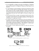
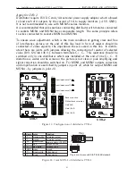
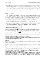
Figure 11: Installation of ferrite core on cables
phone CD-3100 is resistant to such short circuit, however, it should be repaired
as soon as possible. Electronic cassette is preliminarily adjusted and, unless it is
necessary, the position of control elements should not be changed.
In case of need the entry phone should be adjusted after the activation of all uni-
phones.
Then an installation procedure should be started P-3 (see p. 33) and an installation
and activation should be carried out.
6.6
Assembly of MRL-1 modules
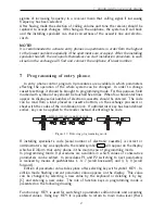
Module MRL-1 is used for connection of more than one panel to one electronic
cassette. Module is used for electronic cassettes operating both main and slave
entrances. Module should be mounted as close as possible to the electronic cassette.
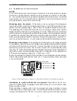
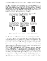
In order to mount MRL-1 module, four screws fixing a cover of casing to its base
should be undone. After removal of cover, holes for fixing screws should be done
in the base. Then it should be placed on the wall and holes for dowels should
be marked. Drill holes in the wall, insert plastic elements of dowels in the holes
and fix the base on the wall with screws. Then connect cables in accordance with
connection scheme and screw down the cover. Module MRL-1 does not require
feeding or any configuration or adjustment.
6.7
Assembly of CVP-2 commutator
Commutator should be mounted in the installation box or in the wall inside the
building, preferably in the installation box together with electronic cassette and
MRL-1 module. To this end, four screws fixing a cover of casing to its base should
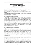
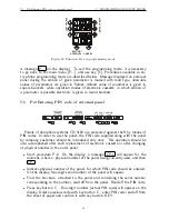
be undone. After removal of cover, holes for fixing screws (W1, W2 - Fig. 12)
should be done in the base. Holes in the wall for dowels should be made and the
base should be fixed to the wall with screws. Then cables should be connected to
clamps ARK in the commutator; plugs in this places of casing cover where cables
will be inserted should be removed by means of pliers and then screw down the
cover to the base.
Output C4+, C4- in the commutator operating at the slave entrance is reserved for
the signal coming from the main entrance.
In order to receive an image, which is free from any deformation, a wiring sys-
tem should be conducted in a proper way as well as input and output impedance of
the installed equipment (monitors, distributors, commutators) should be adjusted
to impedance of the cable used. Load on C1 input should be set on only one from
21

