
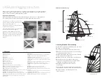
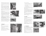

4. Rigging the Trapeze
Please note:
Th
e Laser 2000 trapeze kit is optional and is
not supplied as standard.
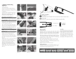
1.
Attach the trapeze wires in the
highest T-terminal position on the mast.
(Previously covered by “Rigging And Raising
Th
e Mast” item 3.)
2.
Ensure the trapeze wires hang down the aft
face of the mast behind the spreaders.
3.
Tie the separate pieces of trapeze shockcord
elastic to the respective port & starboard
gennaker sock “P” clip attachments behind
the jib tack bar. (fi gure 15)
4.
Lead the shockcord elastics down either
gunwale towards the respective shroud anchor
points. (fi gure 16)
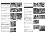
5.
Feed each elastic through the respective
shroud anchor points from the inside-out then
tie a loop in each as shown.
6.
Attach the trapeze rings to hull mounted
shock cords by feeding the elastic loop through
the ring at the bottom of the pulley. (fi gure 17)
7.
Loop the elastic shock cord over the metal
trapeze ring and pull tight. (fi gure 18)
Tip
- Best practice is to tie two double half
hitch stopper knots a hand width apart in the
adjuster line. (fi gure 19)
8.
Shackle the lower shrouds to the lowest cen-
tral hole of the shroud adjusters with the shackle
facing forward as shown. Ensure that a multiple
thickness line of approximately 125 mm in rigged
length is used between the shackle and the hard
eye in the end of each lower shroud wire.
Please Note:
Th
e lower shrouds are part of the trapeze kit
and are not supplied as standard. (
fi gure 20
)
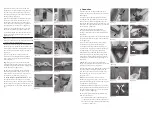
9.
To avoid obstruction, ensure the shackle
pins are fi tted from the inside out. Th
e better
solution would be to discard the shackle pins
and replace them with the pan head machine
screws that are also supplied. (fi gure 20)
10.
Loosely fasten the other end of the lower
shroud wires to the eye on the front face of the
mast using multiple thickness line strops.
(fi gure 21)
11.
Th
e lower shrouds cannot be tuned
and tied off until the jib is hoisted and rig
tension is applied, at which point they should
be adjusted until both wires are equal, JUST in
tension but not pulling the mast aft and tied.
fi gure 19
fi gure 20
fi gure 16
fi gure 22
fi gure 18
fi gure 15
fi gure 21
fi gure 17
12.
Grip tape should be applied parallel to the
gunwale edge commencing approximately
200 mm in front of the shroud anchor points
extending aft. (fi gure 22)
Please Note:
Th
e lower shrouds are supplied to support
the mast and protect it from the loads applied through
use of the trapeze –
the trapeze should never be used
without prior fi tting of the lower shrouds.
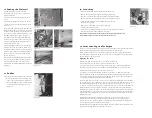
5. Boom and Vang (Kicker)
1.
Unpack the boom.
2.
Attach the boom to the mast as shown.
(fi gure 23)
3.
Ensure the lower vang (kicker) purchase
system is shackled securely to the tang on the
lower aft face of the mast. (fi gure 24)
4.
Hook the vang (kicker) upper purchase
assembly on to the boom ensuring there are
no twists or fouls in the system. (fi gure 25)
5.
Tie the mainsheet through the block on the
mainsheet bridle using a half hitch stopper
knot a shown. (fi gure 26)
6.
Feed the mainsheet through the blocks and
to the mainsheet swivel cleat as shown.
Tip:
Double check the mainsheet passes
through the auto ratchet in the correct
direction shown by the arrow embossed on
the side of the auto ratchet block. (fi gure 27)
7.
Vang (kicker) tension is controlled using
the aft rope and fairlead/cleats on top of the
thwart. (fi gure 28)
Tip:
Best practice is to tie the loose end of the
mainsheet to one of the rear toe straps to pre-
vent tangling and the sheet falling overboard.
(fi gure 29)
6. Jib
1.
Ensure furling drum line is
completely wound onto furling drum
before you attach the jib.
2.
Th
e furling line/cleat can be found on the
starboard side of the foredeck, just in front of
the jib sheet track/cleat. (fi gure 30)
3.
Unroll the jib and attach the jib tack to the
furling drum using the large shackle provided.
(Tape up the shackle and pin to prevent snag-
ging or damage to other sails and lines during
sailing.) (fi gure 31)
fi gure 31
fi gure 27
fi gure 28
fi gure 24
fi gure 26 (aft block)
fi gure 23
fi gure 29
fi gure 25
fi gure 30


