


1.
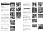
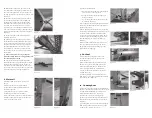
Hatches 1 & 2 are found at the aft edge of the
foredeck. (Fitted to facilitate additional on the
water storage only). (fi gure 1)
2.
Hatch 3 can be found on the inboard surface
of the stern deck. (fi gure 2)
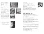
3.
Th
e transom drain bung can be found below
the lower rudder gudgeon. (fi gure 3)
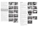
4.
Example of INCORRECT hatch fi tting:
NB:
Correct fi tting of the transom drain bung
and hatch 3, is fundamental to on the water
safety and performance of the Laser 2000.
(fi gure 4)
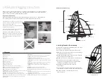
1. Glossary
2. Sailing Number Positioning
Th
e Laser 2000 rigging instructions are a guide to rigging your boat. LaserPerformance
reserves the right to make design and/or specifi cation changes to any of their products
as part of their continuous development program.
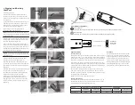
Important information
Th
ere are three hatches and one transom drain bung on the Laser 2000. Every time you
sail, these must be checked to ensure they are closed tightly and fi t correctly.
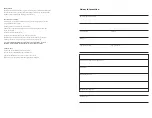
Useful Boat Terminology
It is advised to apply the sail numbers in a dry, clean
and wind-free environment.
1.
Lay the sail on a fl at surface starboard side up.
2.
Numbers on the starboard side of a sail are always
higher than those on the port.
3.
Mark a parallel line 76 mm above the third batten
down from the head of the sail.
4.
Mark a point on the line 76 mm in from the leach.
5.
Th
e fi rst number in the sequence should be
positioned on the parallel line you have drawn
commencing 76 mm in from the leach.
6.
Subsequent numbers should be spaced
60 mm apart.
7.
Turn the sail over and position the port numbers
76 mm below the third batten down from the head.
8.
Work backwards, commencing 76 mm in
from the leach.
fi gure 2
fi gure 3
fi gure 1
fi gure 4
LASER 2000 Rigging Instructions
RUDDER
CENTERBOARD
HULL
BATTENS
LEACH
MAINSAIL
CLEW
FOOT
MAST
SHROUD
GENNAKER
JIB
LUFF
TACK
GENNAKER POLE
76 mm
76 mm
76 mm
60 mm
STARBOARD (RIGHT HAND)
SIDE OF MAINSAIL
Bow:
Front of the boat
Stern:
Back of the boat
Fore:
Forward
Aft:
Rearward
Clew:
Back lower corner of a sail
Tack:
Forward lower corner of sail
Head:
Top corner of sail
Luff :
Forward edge of the sail
Foot:
Bottom edge of the sail
Leech:
Rear edge of the sail
Burgee:
Wind direction indicator (usually a small fl ag)
Batten:
A thin stiff ening strip in the sail to support the leech
Mast:
Main vertical spar supporting the rig/sails
Boom:
Spar at the bottom of the mainsail
Gennaker pole:
Th
e pole that extends from the bow to fl y the gennaker sail
Cleat:
A fi tting used for holding /securing lines
Forestay:
Th
e wire supporting the mast at the bow of the boat
Shrouds:
Wires that hold the mast in the boat and support it from ¾ up and
out to hull side; they attach with shroud adjuster to shroud anchor point
Lower shrouds:
Wires that tie off ¼ up mast and shackle to shroud
anchor points
Jib:
Front sail
Sheet:
Rope for controlling the inward/outward position of the sail
Gennaker:
Isometric sail hoisted when sailing downwind
Gunwale:
Th
e outermost edge of the boat
Gudgeon:
Fitting on the transom and rudder used to hang rudder
Cunningham:
Purchase system for tightening the forward edge/luff
of the sail
Gnav:
Purchase system for tightening the rear edge/leach of the sail
Vang (kicker):
Otherwise known as the kicking strap or Gnav
Outhaul:
Purchase system for tightening the bottom edge/foot of
the sail
Halyard:
A rope or wire used to lower or hoist sails
Mast Heel:
Fitting on the bottom edge/foot of the mast
Mast step:
Fitting on the boat where the mast heel/foot of the mast
is located
Spreaders:
Metal struts placed in pairs to support the mast side ways
and control the bend in the mast
Stem fi tting:
Stainless fi tting at the bow to which the forestay attaches
Rudder:
Blade and attachments used for steering the boat


