background image

ICS-7-OEM Instruction Manual 


02058-53-000 

Page 16 of 29


Issue 3          19 January 2021 


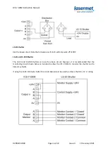
LS-10 Shutter 

 
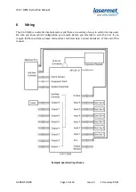
Use the above circuit. Note that old versions of LS-10 will only work off 12VDC. 
 

LS-20 and LS-200 Shutter 

 
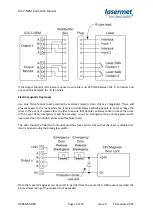
The  LS-20  and  LS-200  Shutters  can  use  the  above  circuit;  however,  it  is  recommended  that  the 
monitoring  circuit  shown below  is  included  to  allow  the  ICS-7-OEM  to  monitor  the  shutter  and  to 
detect any faults. 
 
If using the LS-20 SIL3 twin shutter the circuit below must be used to achieve the SIL3 / PL ‘e’ rating. 


Summary of Contents for ICS-7-OEM

Page 1: ...ICS 7 OEM Instruction Manual 02058 53 000 Issue 3 19 January 2021 LASERMET ICS 7 OEM INSTRUCTION MANUAL FAIL SAFE LASER INTERLOCK CONTROLLER...

Page 2: ...7 OEM Illuminated Sign Control Output 14 6 3 Interlock Operator Output Contacts 15 7 Expansion Boards 20 7 1 Installing Expansion Boards 21 7 2 Use with Active Guarding 21 7 3 Expansion Board Fault Ou...

Page 3: ...ies with the basic requirements for health and safety as provided by the following directives and standards Directives Machinery Directive 2006 42 EC June 2010 Low Voltage Directive 2014 35 EU EMC Dir...

Page 4: ...fixing holes They must not come into contact with each other or any other moving part when in use The parts should never be subject to impact or mechanical strain Safety switches should never be defe...

Page 5: ...mance level e Eight safety interlock outputs each rated at 4A resistive 50VDC are provided to enable the laser operate door locks or provide signals to a PLC The interlock outputs are volt free contac...

Page 6: ...ny queries Contact details are given at the end of this manual 3 1 Differences between ICS 7 OEM and ICS 6 OEM Power supply to expansion modules is now switched on in the disarmed state allowing visua...

Page 7: ...be wired as described in this manual using suitably rated door sensors and measures taken to minimise the effects of common cause failures in the sensors and wiring which may be connected to the unit...

Page 8: ...sition for wiring It should be inaccessible by operators It has indicator lights on its top surface which would normally only need to be observed by installation and maintenance personnel Provision sh...

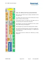
Page 9: ...controller All dual channel inputs and outputs are wired ABBA with one channel connected A A and the other channel B B Input signals are connected on the right bottom of the controller and are indica...

Page 10: ...satile interlock system and there are a variety of ways in which it can be used Be sure you know which configuration you require before you attempt to wire the unit If you require further assistance p...

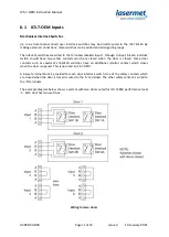
Page 11: ...lock switch should have two safety contacts which are closed when the door is closed Some door contacts such as Lasermet s IS MECH switches have an additional monitor contact which closes when the doo...

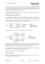
Page 12: ...ls Fit a wire link across the B terminals The Mismatch Detector cannot be used and must be disabled see the Mismatch Detector section below It is usual to use low voltage 4 core flexible cable for the...

Page 13: ...cts which open when the button is pressed 2NC Connect one safety contact which opens when the button is pressed to the A terminals of the E STOP terminal block Connect the other safety contact to the...

Page 14: ...er is armed One of the seven normally open outputs of the ICS 7 OEM is used to illuminate the sign This output must not then be used to operate a laser interlock as well Option 2 Two way Illuminated W...

Page 15: ...directly wired to the ICS 7 OEM Where there is any possibility of the equipment being changed or moved it is often most convenient to be able to unplug the equipment Lasermet provide a range of small...

Page 16: ...l only work off 12VDC LS 20 and LS 200 Shutter The LS 20 and LS 200 Shutters can use the above circuit however it is recommended that the monitoring circuit shown below is included to allow the ICS 7...

Page 17: ...t the shutter closes when the Interlock Operator contact opens Any ICS 7 OEM output used for shutters must not also be used for laser interlock control The contact is limited to 4A resistive load If y...

Page 18: ...13849 1 and feature two interlock input channels This will require a distribution plug and socket with more connections Furthermore some lasers also include one or two laser safe contacts which can be...

Page 19: ...ile always allowing people to enter or leave the room in the event of a power loss In order to ensure that people can always enter or leave the room in the event of an emergency it will be necessary t...

Page 20: ...used with lasers which are potentially capable of damaging or burning through their enclosures The enclosure is lined with replaceable active detection panels If the laser burns through the panel it...

Page 21: ...s to be seen On closing the Arm inputs the switched 24V supply is switched off momentarily to test the operation of the Active Guarding circuits then switched back on if the test succeeds NOTE This be...

Page 22: ...ote that the use of a single channel safety contact and the disabling of the mismatch detector will reduce the achievable safety performance level of the system 8 1 Configurable Options for Safety Cir...

Page 23: ...lus interface card generates a mismatch event during its start up sequence so if this expansion card is being used the pre check mismatch detection must be disabled by setting Option 3 to On Mismatch...

Page 24: ...the system has been wired up For each Interlock a pair of yellow LEDs indicate that the interlock is open If the contact is not used and a wire link has been fitted the corresponding LED will not ill...

Page 25: ...is triggered which disables the system and illuminates a red Fault light on the front panel The Mismatch Detector also monitors the internal relays of the controller and the safety proving contacts o...

Page 26: ...illuminated in yellow This may occur if an expansion board has detected a fault or if the expansion socket is open and no termination plug has been fitted 10 Operation Once correctly wired the ICS 7 O...

Page 27: ...s power to the shutters or the laser and may result in accessible laser beams depending on your system set up This action should only be taken when everyone is ready and the necessary safety precautio...

Page 28: ...Weight 0 8kg Dimensions are approximate Values given as typical are average values measured across a number of samples and are not guaranteed Lasermet reserve the right to alter any specification wit...

Page 29: ...ovide a complete system We also supply equipment and consultancy covering all aspects of laser safety Full support design and installation is available from Lasermet please contact us for any queries...

Reviews: