


ICS-6 Instruction Manual
01000-53-000
Page 9 of 42
Issue 11 19 January 2021
4
Installation
The ICS-6 is designed to be permanently attached to a wall or other fixed vertical surface.
The ICS-6 should be mounted in a convenient position for use and wiring. During use it will be
necessary for operators to access the controls and to observe the indications.
For rooms where personnel may work inside while the laser is operating this is often near the main
entry door, but it can be near the working position within the room if preferred. For enclosures
which personnel leave before activating the laser, the ICS-6 may be fitted on the outside of the
enclosure itself or somewhere convenient nearby.
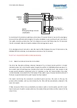
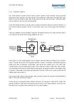
During installation, wired connections will need to be made from the ICS-6 to all the interlocked
doors, warning signs, laser interlocks, shutters and other equipment as required by the system, and
allowance should be made for the installation of electrical conduits, trunking etc. to make entry to
the unit.
There should be adequate clearance beneath the unit to allow the front door to be fully opened
downwards. Installation will be impaired if the door cannot be fully opened. Care should be taken
that any conduit or trunking beneath the unit will allow the door to open sufficiently.
To open the unit, unlock the catch by turning the lock with a flat screwdriver until the slot is
horizontal. Press the release bar downwards and the cover will unlock. It can then be hinged
downwards and will snap into the upright position.
Four Ø5mm fixing holes are provided in the four corners of the case for mounting purposes.
The cables for mains supply, door switches, laser control etc. are usually fed to the unit through
plastic trunking or 22mm diameter plastic conduit, and holes are required to be made in the case to
accommodate the entry points. An electrician’s conduit hole cutter is the ideal tool for this purpose.
The conduit may be surface mounted or buried in the wall and should be arranged to ensure that
holes can be made in the enclosure in the required positions. If surface-mounted conduit is used the
top and bottom faces of the case will usually be found to provide the most convenient entry points.
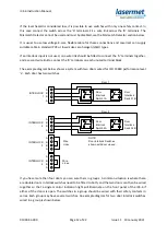
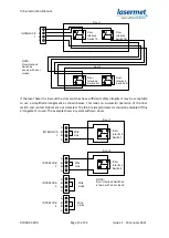
All connections are made on the narrow circuit board located in the bottom of the case. All of the
terminals are identified on the circuit board.
The connection circuit board may be temporarily removed during installation. With the exception of
the 9-way Interlock option in the shallow case, the board can also be refitted in any of three
different locations in the case to suit the cable entry points.
Care should be taken in the running of conduits that the proposed entry position in the ICS-6 can be
accommodated and that the front cover of the ICS-6 can be opened.


