


ICS-6 Instruction Manual
01000-53-000
Page 14 of 42
Issue 11 19 January 2021
5.2.2
Coded Magnetic Interlock Switches
Coded magnetic switches supplied by Lasermet cannot be overridden by the use of a magnet. Wire
the safety circuits in the same way as described in the 'Mechanical Interlock Switches section. The
monitor contacts should not be used.
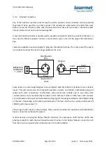
The Lasermet IS-MDC-12 is a dual channel magnetic door switch. If the mismatch detector is used in
the ICS-6, any single contact failure in the door switch will be detected and the laser inhibited. In this
switch the red and blue wires are taken to the ‘A’ terminals and the black and white wires to the ‘B’
terminals. The green and yellow wires are not used.
For the highest level of safety two separate door switches may be used, one wired to the ‘A’
terminals and one to the ‘B’ terminals.
If the laser hazard is low and the door switches have sufficient safety integrity it may be acceptable
to use the simplified arrangement described in the Mechanical Interlock Switches section above.
5.2.3
Emergency Stop and Break Glass Switches
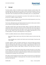
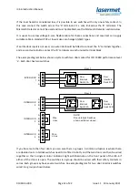
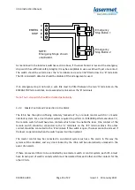
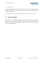
The ICS-6 treats Emergency Stop switches in the same way as Door Interlock switches. Ideally the
Emergency Stop switch should have two contacts which open when the button is pressed (2NC).
Connect one safety contact, which opens when the button is pressed, to the ‘A’ terminals of the
EMERG STOP terminal block. Connect the other safety contact to the ‘B’ terminals.
A
B
B
A
EMERG
STOP
Emergency
Stop Button
NOTE:
Emergency Stop shown
unactivated.
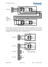
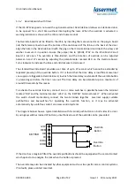
If there are two or more switches, connect the contacts in series as shown below.


