


ICS-TOUCH Instruction Manual
CEB00XXX-53-000
Page 21 of 43
Issue 4 19 January 2021
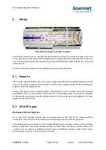
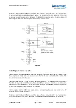
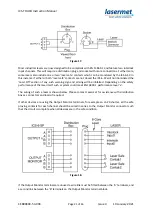
Figure 17.
Most industrial lasers are now designed to be compliant with EN 13849-1 and feature two interlock
input channels. This will require a distribution plug and socket with more connections. Furthermore,
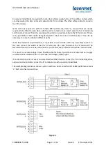
some lasers also include one or two ‘laser safe’ contacts which can be monitored by the ICS-6-SP. In
this instance if either or both ‘laser safe’ contacts are not closed the ICS-6-SP will not illuminated the
‘Laser Off’ section of any such warning sign and arming will be inhibited. Depending on the safety
performance of the laser itself such a system could meet EN 13849-1 performance level ‘e’.
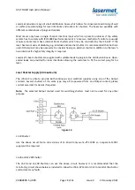
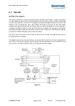
The wiring of such a laser is shown below. Please contact Lasermet for assistance with distribution
boxes, connectors and leads if required.
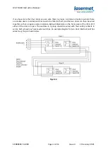
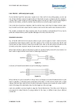
If other devices are using the Output Monitor terminals, for example an LS-20 shutter, all the safe
proving contacts for each channel should be wired in series to the Output Monitor connector such
that the circuit is complete when all devices are in the safe condition.
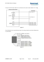
Figure 18.
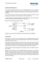
If the Output Monitor terminals are unused a wire link must be fitted between the ‘A’ terminals, and
a second link between the ‘B’ terminals on the Output Monitor terminal block.


