ICS-TOUCH Instruction Manual
CEB00XXX-53-000
Page 14 of 43
Issue 4 19 January 2021
Emergency Stop and Break Glass Switches
The ICS-6-SP treats Emergency Stop switches in the same way as Door Interlock switches. Ideally the
Emergency Stop switch should have two contacts which open when the button is pressed (2NC).
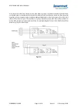
Connect one safety contact, which opens when the button is pressed, to the ‘A’ terminals of the E-
STOP terminal block. Connect the other safety contact to the ‘B’ terminals.
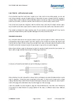
Figure 5.
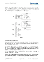
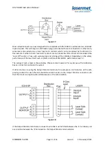
If there are two or more switches, connect the contacts in series as shown below.
Figure 6.
As mentioned in the interlock switches section above, if the laser hazard is low and the emergency
stop switch has sufficient safety integrity it may be acceptable to use a switch with just one contact.
The switch should be wired across the ‘A’ terminals and a wire link fitted across the ‘B’ terminals.
The ICS-6-SP mismatch detector should be disabled if this arrangement is used.
If an emergency stop is not used, a wire link must be fitted between the two ‘A’ terminals on the E-
STOP terminal block, and a second wire link across the ‘B’ terminals.
Note:
The emergency stop switch should be checked periodically.

