Laser 5091 Instructions Manual Download Page 8

Laser 5091 Code Reader User’s Guide

14

Laser 5091 Code Reader User’s Guide

15

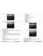
Figure 4-13 Sample Live Data Menu Screen 

2. The custom datastream selection screen displays.

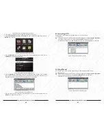
Figure 4-14 Sample Custom Datastream Selection Screen 
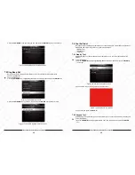
3. Use the 

RIGHT

 key to select or deselect a line or press 

LEFT 

key to deselect all if needed .

Press the 

ENTER

 key to confirm and 

BACK

 key to cancel. 

Figure 4-15 Sample Custom Datastream Screen 

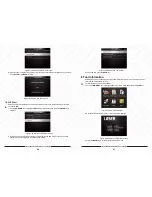
4. When finished selection, press the 

ENTER

 key to display selected items.

4.3.1.2 Custom Data List 

Custom Data List menu lets you to minimize the number of PIDs on the data list and focus on any 

suspicious or symptom-specific data parameters.


To create a custom data list: 

1. Select 

Custom List

 from the menu and press the 

ENTER

 key.

Figure 4-16 Sample Datastream Screen 
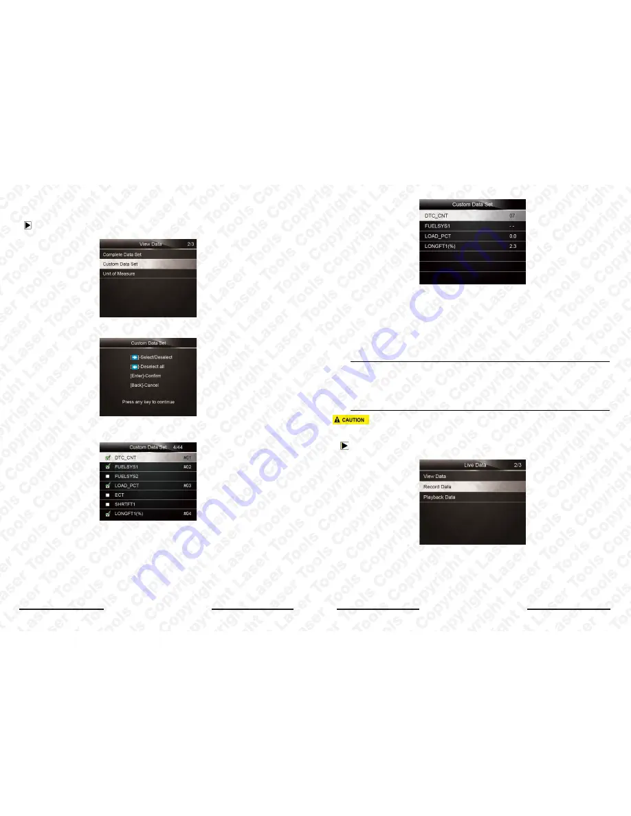
4.3.2 Record Data 

The 

Record Data

 function is used to record PIDs to help diagnose intermittent drivability problems that 

can’t be determined by any other method.

Menu options typically include: 

Complete Data

Custom Data

Unit of measure (Please refer to Chapter 7 

Set Up

)

NOTE


There are two types of trigger methods used. 

Manual Trigger---triggers recording whenever operators press the 

ENTER

 key.

DTC trigger--- automatically triggers recording when a code is detected by vehicle. DTC Trigger

is not available on all vehicles. Some vehicles need to be driven for a long period of time to store

a code after a drivability fault occurs. If 

DTC trigger 

is selected to make a recording, there might

not be drastic change in the data before and after trigger.

Do not operate the code reader while driving; always have two persons in vehicle when recording – one 

to drive and the other to operate the code reader. 
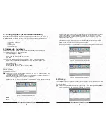
To record data: 

1. Select 

Record data 

from the menu and press the 

ENTER

 key.

Figure 4-17 Sample Live Data Menu Screen 

2. Refer to

 View Data

 to set up 

Complete Data Set

 or 

Customer Data Set

 to record.

Summary of Contents for 5091

Page 1: ...ader The CAN OBDII EOBD Code Reader is an innovative and affordable solution specially designed for the owner to get easy and quick access to engine problems on all OBDII compliant petrol vehicles 200...

Page 2: ...n areas where explosive vapor may collect such as in below ground pits confined areas or areas that are less than 18 inches 45 cm above the floor Do not smoke strike a match or cause a spark near the...

Page 3: ...hen System Setup is selected a menu that lists all available options displays Menu options include Languages Configure monitors Unit of measure Key Beep Set Diag Beep Set Tool self test 1 2 2 Arrow Ic...

Page 4: ...y of the following items missing from your package contact your local dealer for assistance 2 1 Code Reader Descriptions 1 User s Guide provides operation instructions for the usage of the code reader...

Page 5: ...e applicable to all vehicles Available options may vary by the year model and make of the test vehicle A The selected mode is not supported message displays if the option is not applicable to the vehi...

Page 6: ...automatically according to the VIN 4 2 Erase Codes Erase Codes menu lets you to clear all current and stored DTCs from the control module Also it erases all temporary ECU information including freeze...

Page 7: ...supported PIDs of the vehicle being tested To view all live PID data 1 Use the UP DOWN key to highlight Live Data from Diagnostic Menu and press the ENTER key Figure 4 8 Sample Diagnostic Menu Screen...

Page 8: ...o record PIDs to help diagnose intermittent drivability problems that can t be determined by any other method Menu options typically include Complete Data Custom Data Unit of measure Please refer to C...

Page 9: ...dicates that a recording currently exists in this memory location If an area with an asterisk was picked a message prompting to erase data displays Figure 4 21 Sample Erase Recording Screen 5 If the r...

Page 10: ...ple Record Data Screen 2 Use the UP DOWN key to select a memory area that is marked with an asterisk and press the ENTER to confirm Figure 4 27 Sample Record Data Screen 3 Press the UP DOWN key to vie...

Page 11: ...ported by all vehicles To retrieve I M Readiness Status data by one click I M readiness key 1 Press the One Click I M Readiness Key on the keypad and the following screen displays Figure 4 30 Sample D...

Page 12: ...ts The O2 Monitor Test function is used to retrieve completed O2 sensors monitor test results The O2 Monitor Test is not an on demand test O2 sensors are not tested when selected via the menu but test...

Page 13: ...ssion related powertrain components and systems that are and are not continuously monitored It is vehicle manufacturer who is responsible for assigning test and component IDs NOTE Test results do not...

Page 14: ...f available tests displays Figure 4 43 Sample Diagnostic Menu Screen 2 Use the UP DOWN key to highlight a system or component press the ENTER key to start test and the code reader displays the message...

Page 15: ...0 Modules Present The code reader identifies module IDs and communication protocols for OBD2 modules in the vehicle To view module IDs and communication types 1 Use the UP DOWN key to highlight Module...

Page 16: ...e 6 1 Sample Home Screen 2 A screen with a list of test records displays If no data is recorded the message No Data available is displayed Figure 6 2 Sample Playback Screen 3 Use the UP DOWN key to hi...

Page 17: ...ntinuous Monitors Misfire Fuel System Comprehensive Component Non Continuous Monitors NOTE Non continuous monitors are different for spark ignition cars petrol gasoline engines and compression ignitio...

Page 18: ...to confirm Figure 7 7 Sample Configure Monitors Display 2 The custom monitors selection screen displays and Use the RIGHT key to select or deselect a monitor or press the LEFT key to deselect all the...

Page 19: ...rompting to reset factory default displays Answer Yes to confirm the request or answer No to abort and return Figure7 11 Sample Reset Factory Default Screen 7 3 Unit of measure Unit of measure opens a...

Page 20: ...est 7 6 1 Display Test Selecting Display Test option opens a screen that allows you to check the functionality of the display To test the display 1 Use the UP DOWN key to highlight Display Test from S...

Page 21: ...7 22 Sample Tool Self test Screen 2 Scroll with the up and down arrow keys to select the desired LED lamps to check The LED should turn on off according to the selected commands Figure 7 23 Sample LE...

Page 22: ...ow instructions on computer screen to install the tool and driver 3 Double click the desktop icon to launch the application 4 Connect 5091 to computer with the USB cable provided 5 Press and hold the...

Page 23: ...or to the edit box Figure 9 7 Sample Printing Data Screen 7 With the printer correctly connected use the Print key to print the testing data Press the BACK key to return to home screen 9 3 Searching D...

Page 24: ...016 The Tool Connection Limited All rights reserved Disclaimer The information specifications and illustrations in this manual are based on the latest information available at the time of printing The...

Page 25: ...www lasertools co uk...

Reviews: