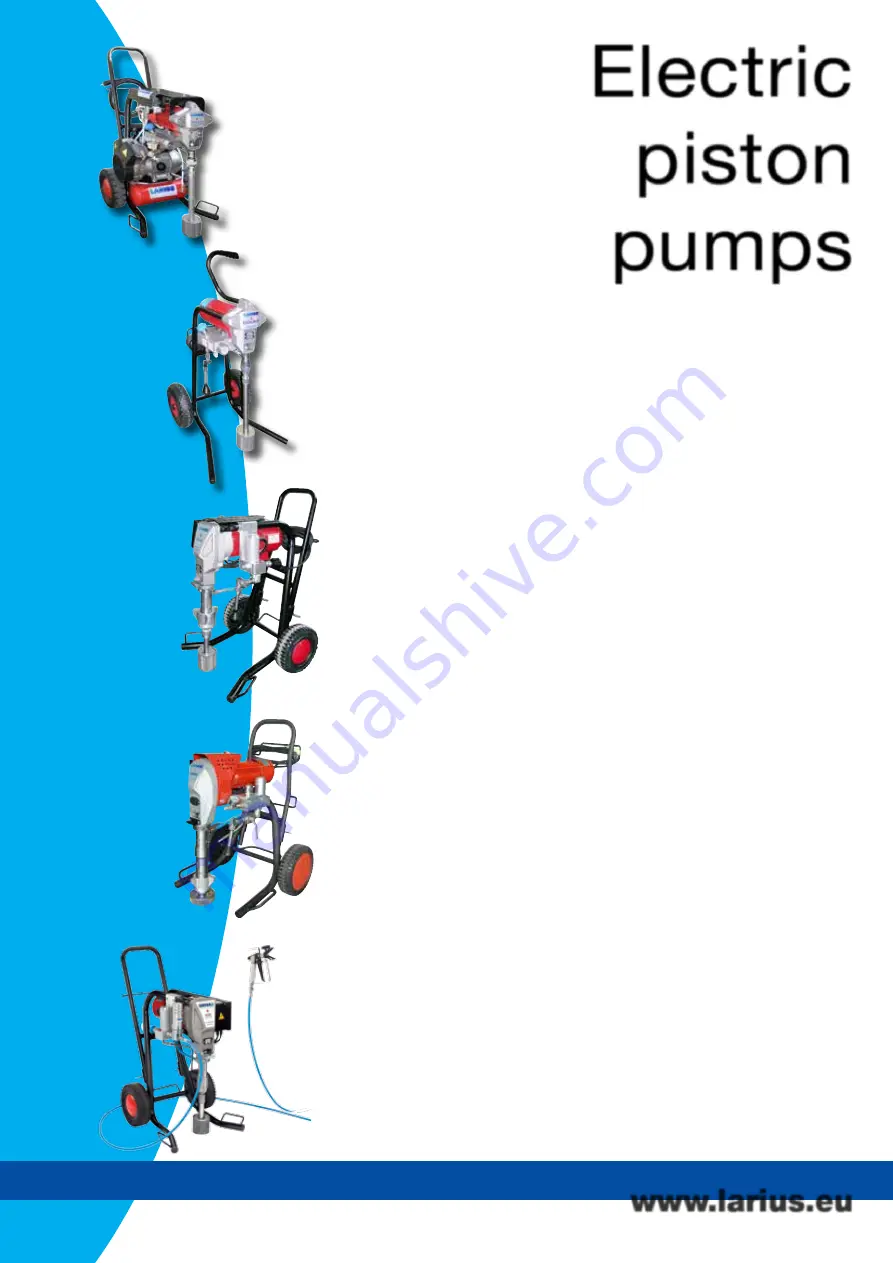
Electric
piston
pumps
NEW EXCALIBUR
Version on trolley Rif. 18776
DRAGON
Rif. 30184
JOLLY
Top finish version Rif. 18774/1
ZEUS
Rif. K35100
THOR
220V/50Hz
Long pumping unit Rif. 20705
Short pumping unit Rif. 20700
www.larius.eu
Page 1: ...ITALIANO Ed 015 02 2019 www larius eu OPERATING AND MAINTENANCE INSTRUCTION Electric piston pump NEW EXCALIBUR ...
Page 2: ...umps NEW EXCALIBUR Version on trolley Rif 18776 DRAGON Rif 30184 JOLLY Top finish version Rif 18774 1 ZEUS Rif K35100 THOR 220V 50Hz Long pumping unit Rif 20705 THOR 220V 50Hz Short pumping unit Rif 20700 www larius eu ...
Page 3: ...Electric diaphragm pumps VIKING Rif 18741 MIRO Rif 21500 GIOTTO Rif 12450 DALI Rif 18900 www larius eu ...
Page 4: ... manual without prior notice This manual is to be considered as an English language translation of the original manual in Italian The manufacturer shall bear no responsibility for any damages or inconveniences that may arise due to the incorrect translation of the instructions contained within the original manual in Italian ...
Page 5: ...aintenance p 23 Replacing the foot valve seals p 23 Replacing the pump unit housing gasket p 24 Replacing the pump unit stem gasket p 26 Correct positioning of the pump unit p 29 spare parts RECIRCULATING SAFETY VALVE GROUP REF 16400 p 35 REDUCTION GEAR p 36 FRAME p 37 TROLLEY p 37 ELECTRO CONTROL DEVICE HYDRAULIC COMPLETE REF P 38 18770 AND 18771 p 38 COMPLETE PUMPING GROUP p 40 TOP FINISH ASSEMB...
Page 6: ...es wound and finger squashing risk due to movable parts in the equipment Tenersi lontano dalle parti in movimento Do not use the equipment without the proper protection Before any inspection or maintenance of the equipment carry out the decompression procedure explained in this manual and prevent any risk of the equipment starting unexpectedly Report any risk of chemical reaction or explosion if t...
Page 7: ...ss derives the term airless The pump is controlled by an electric motor coupled with a reduction gear Acamshaftandaconnectingrodallowtoobtainthereciprocating motionnecessarytotheworkingofthe pumpinggroup piston The piston movement produces a vacuum The product is sucked pushed towards the pump outlet and then sent to the gun through the flexible hose A electronical device on the side of the reduct...
Page 8: ...chro nous 0 75 kW 210 bar 2 1 L min M16 x 1 5 M 0 023 17 Kg 80dB A A 450 mm B 460 mm C 550 mm 0 40 Mpa 4 0 Kw monophase NEW EXCALIBUR 230Vac 50Hz minimum 4Kw asynchro nous 0 75 kW 210 bar 2 1 L min M16 x 1 5 M 0 023 18 Kg 80dB A A 580 mm B 540 mm C 995 mm 0 40 Mpa 4 0 Kw monophase 230Vac 50Hz minimum 4Kw asynchro nous 0 75 kW 210 bar 2 1 L min M16 x 1 5 M 0 023 65 Kg 80dB A A xx mm B xx mm C xx mm...
Page 9: ...Ed 015 02 2019 www larius eu NEW EXCALIBUR 5 Top Finish version Frame mounted Trolley mounted C A B B A C C A B ...
Page 10: ...ion filter 5 Plug filter 6 Pumping group 7 ON OFFswitch 8 Potentiometer for adjusting the operating pressure POS Description 9 Intake product pipe 10 Attack for product delivery 11 Indicator light alarms 12 Airless manual gun 13 Trigger safety clamp 14 Reduction box 15 Handle 16 Frame Frame mounted DESCRIPTION OF THE EQUIPMENT 13 12 9 7 8 14 4 2 3 5 6 1 10 15 16 ...
Page 11: ... larius eu NEW EXCALIBUR 7 20 21 19 18 17 22 Press here to unlock POS Description 17 Recirculation piping with fittings 18 Union 19 Dip hose POS Description 20 Trolley 21 Wheel 22 Unlocking manual device Trolley mounted ...
Page 12: ...CALIBUR 8 24 23 26 29 27 28 24 POS Description 23 Version Top Finish 24 Air regulator 25 Air tank 26 Mist less 09 hand gun 27 Carter POS Description 28 Compressor unit 29 Wheels 30 Pressure switch 31 Manometer 30 31 25 Top Finish version ...
Page 13: ...Ed 015 02 2019 www larius eu NEW EXCALIBUR 9 ...
Page 14: ...s about allthoserisksstemmingfromaccidents about the use of safety devices for their own safe ty and about the general rules for accident prevention in compliance with international regulations and with the laws of the country where the plant is used Read carefully and entirely the following instruc tions before using the product Please save these instructions in a safe place The unauthorised tamp...
Page 15: ...RODUCT TO BE USED IS TOXIC AVOID INHALATION AND CONTACT BY USING PRO TECTION GLOVES GOGGLES AND PROPER FACE SHIELDS TAKE PROPER SAFETY MEASURES FOR THE PROTECTION OF HEARING IN CASE OF WORK NEAR THE PLANT Electrical safety precautions Checktheswitchisonthe OFF positionbeforeconnecting the cable to the mains Never carry a plugged in equipment Disconnect the equipment before storing it and before pe...
Page 16: ...repaired flexible hose CHECK ON POWER SUPPLY Make sure that the electrical system is earthed and complies with regulations Check the mains voltage corresponds to the equipment s rating The supply cable is provided without plug Use a plug which guarantees the plant earthing Only a technician or a skilled person should perform the connection of the plug to the electric cable Should anyone use an ext...
Page 17: ...t ON I Turn clockwise the pressure control knob F5 so as the machine works at idle speed CONNECTION OF THE TOOLING TO THE POWER SUPPLY Check the switch F4 is on the OFF 0 position before connecting the cable to the mains Place the pressure control knob F5 on the MIN position turn counterclockwise OFF F4 F5 ON F4 F5 F3 ...
Page 18: ...e to stop the pump Closed the recirculating safety valve F6 Turn pressure regulating knob F5 clockwise a little so that the machine idles Open the recirculating safety valve F6 Turn the pressure setting knob F5 clockwise to the CIR CULATION WASHING position drop symbol OPEN It re circulates back into the tank without spraying CLOSED It sprays out of the spray gun Circulation and washing F6 F6 F5 F...
Page 19: ...act between the solvent fumes and the electric motor Never use products containing halogen hydrocarbons as methylene chloride If these products come into contact with aluminium parts of the equipment can provoke dangerous chemical reactions with risk of explosion Make sure the product to be used is compatible with the materials employed for manufacturing the equipment stainless steel and aluminium...
Page 20: ...ch ON I of the equipment and turn a little thepressurecontrolknobclockwise G3 soasthemachine works at the idle speed SPRAY ADJUSTMENT Slowly turn clockwise the pressure control knob to reach the pressure value in order to ensure a good atomization of the product An irregular and marked spray on the sides indicates a low working pressure On the contrary a too high pressure causes a high fog overspr...
Page 21: ...gger of the gun and pointing it into a container Open the recirculating safety valve H3 to release the pressure in the circuit Lift the suction pipe and replace the product tank with that ofthesolvent ensureitiscompatiblewiththeproductbeing used Unscrewthegunnozzle donotforgettocleanitwithsolvent Press the switch H2 ON and turn a little the pressure control knob H1 clockwise so as the machine work...
Page 22: ...DICALLY Check the pumping gaskets draft if the product draws replace gaskets Clean the mobile parts from the varnish deposits spray guns etc Checkthatthetubesandallthefittingsarecorrectlylocked Discharge the pressure in the pump unit open the discharge valve before carrying out any maintenance ROUTINE MAINTENANCE CHECK ON THE PACKING NUT Daily check the packing nut is tight in order to avoid waste...
Page 23: ...Ed 015 02 2019 www larius eu NEW EXCALIBUR 19 M Code 16801 Code 16858 Code 16859 Code 16850 Code 18044 Code 16854 Code 16856 Code 32038 Code 16852 WARNING PLATE ...
Page 24: ...valve dirty Nozzle too big or worn The product is too dense The filter of the gun butt is too fine The nozzle is partially clogged The product is too dense The filter of the gun butt is too fine The nozzle is worn The gaskets of the pumping group are worn Suction or delivery valve dirty Recirculating safetyvalvedefective Check the correct connection to the power supply Check the extension cable En...
Page 25: ...oosen very slowly the fitting of connection from the flexible hose to the gun Clean or replace the flexible hose and the nozzle Move the switch O2 to the OFF position to stop the equipment Reduce pressure to the minimum turn counterclockwise the pressure control knob O3 Disconnect the power supply cable O4 Release the gun clamp O1 point the gun into the tank of the product and press the trigger to...
Page 26: ...move it Remove the locking pin P5 using pliers P6 Unscrew the fixing ring nut P7 to the end of the thread using a 45 mm spanner Unscrew the suction casing using a 32 mm spanner as illustrated Ifnecessary removethesuctionpipe P8 before continuing with the other operations Use a 19 mm spanner to unscrew the ring nut P1 on the feed pipe in order to make the operation easier Always disconnect the powe...
Page 27: ...d Turn anticlockwise as shown Use a 36 mm spanner to unscrew the pump unit as shown Remove the pump unit P13 from the foot valve P14 as shown Inspect the two parts separately PIT STOP MAINTENANCE Replacement of upper and lower gaskets 25 minutes REPLACING THE FOOT VALVE SEALS Replace the PTFE gasket P15 located under the ball seating P16 Check that the surfaces of the ball seating P16 and the ball...
Page 28: ...the piston stem P18 from the pump unit housing P19 as shown Unscrewthegasketcompressionringnut P20 completely All the gaskets in the unit must be replaced at the same time to allow the machine to work properly Remove the upper stainless steel female ring P21 as shown P16 P15 P17 P18 P19 P20 P21 P21 ...
Page 29: ...skets contained inside the pump unit housing as shown Removethelowerstainlesssteelmalering P22 asshown Fitthenewgasketkitaccordingtothecomponentsequence shown in the figure Upper white PTFE Grey polyethylene Waxed leather Grey polyethylene Lower white PTFE 1 2 P22 3 4 5 ...
Page 30: ...3 and replace it with a new one P24 REPLACING THE PUMP UNIT STEM GASKET Secure the stem P19 in a vice as shown Waxed leather Code16155 Steel male ring Code 16108 Polyethylene grey Code 16124 PTFE white Code 16107 Steel female ring Code 16106 Polyethylene grey Code 16124 PTFE grey Code 16107 ...
Page 31: ...8 Replace if necessary Use a 10 mm spanner to unscrew and remove the stem P19 as indicated Removethecompletegasketkit P25 fromthestem P19 as shown in order to replace it L O W ER Steel male ring Code 18644 Steel female ring Code 18645 PTFE white Code 16117 Polyurethane red Code 16114 PTFE White Code 16117 Polyethylene grey Code 16136 PTFE scraper ring Code 18648 ...
Page 32: ...16126 with grease as shown Vaseline is recommended for this task Replace the grey polyethylene lipped gasket P26 for the valve piston Refit according to the assembly order and the alignment of the lip as shown Checkthesurfacesoftheball P27 andballseating P28 and replace both if damaged Assemble the components as shown Lubricate the gaskets P29 and the stem Vaseline is recommended for this task P19...
Page 33: ... previously complete a full stroke as shown Usethepin P12 suppliedtotightenthegasketcompression ring nut P11 Close this until it is fully touching without forcing CORRECT POSITIONING OF THE PUMP UNIT Once the unit has been refitted proceed as follows Check the position of the con rod which should be posi tioned at its lower stopping point Put the entire pump unit P10 inside the reduction cover P33...
Page 34: ...rod P34 Check that the closing spring P36 in the con rod P34 goes into the pin seating when closed as shown Screwtheentirepumpunit P10 insidethereductioncove The reference value see drawing must be 18 mm The maximum tolerance accepted for correct ope ration is 21 mm maximum and 16 mm minimum Use a gauge to measure the gap between the base of the template and the start of the tightening groove P10 ...
Page 35: ...s shown X1 P40 For correct reassembly see the exploded diagram for the pump unit and invert the order used for disassembly Once the unit has been positioned correctly tighten the lock nut P37 hard against the front template To tighten use a 45 mm spanner Close the inspection cover P2 again Fit the suction pipe P8 Put PTFE tape or liquid PTFE over the threaded part P39 before screwing it onto the f...
Page 36: ...RE PARTS FRAME MOUNTED O U O V O R O Q Complete electro hydraulic control device Ref 18770 and 18771 Page 38 Drive assembly page 36 Recirculating safety valve group ref 16400 Page 35 Complete pumping page 40 Electric motor page 48 O AD Accessories page 49 O S Frame pag 37 O AC ...
Page 37: ...SPARE PARTS TROLLEY MOUNTED O U O V O Q O AD O R O T Trolley page 37 O AC Complete electro hydraulic control device Ref 18770 and 18771 Page 38 Drive assembly page 36 Recirculating safety valve group ref 16400 page 35 Complete pumping page 40 Electric motor page 48 Accessories page 49 ...
Page 38: ...afety valve group ref 16400 page 35 O AD Accessories page 49 O R Drive assembly page 36 Electric motor page 48 X Compressor page 43 AIR TANK page 46 PRESSURE page 44 O Y Trolley page 47 O Z AIR REGULATOR page 45 O W Assembly page 42 O AB O AA O AC SPARE PARTS TOP FINISH VERSION SPARE PARTS TOP FINISH VERSION O V Complete pumping page 39 ...
Page 39: ...up 1 4033 OR 2062 2 16415 Valve housing 3 53007 3 OR 2018 4 16419 Ring BK 2018 5 16420 Complete rod 6 16410 Spring 7 16409 Clamping ring 8 16408 Pin 9 16405 Knob Q RECIRCULATING SAFETY VALVE GROUP REF 56563 for all versions 1 2 3 4 5 7 8 9 6 WARNING Always indicate code and quantity for each part required ...
Page 40: ...leeve 5 18663 Cover 6 18672 Complete toothed gear 7 18680 Complete toothed driving gear 8 18673 Complete connecting rod 9 18667 Cam bushing 10 18681 Driving cam 11 18665 Spring 12 18664 Bushing 13 4233 Centering pin Pos Code Description 14 18685 Scraper ring 15 18666 Pin for connecting rod 16 18629 Tin plate door 17 9173 Screw 18 18790 Completeh p hoseforconnection 19 8029 Screw 20 32005 Washer 23...
Page 41: ... Frame tube left 4 18698A Frame tube right 5 37403 Frame cap 9 3 Pos Code Description 1 18765 Handle 2 18631 Handgrip 3 37406 Screw 4 34009 Washer 5 7059 Screw 6 91047 Washer firm wheel 7 37218 Wheel 8 18632 Frame 9 37403 Caps 2 1 8 5 5 9 7 6 7 6 4 4 4 T TROLLEY WARNING Always indicate code and quantity for each part required ...
Page 42: ...7 18 19 20 21 19 23 24 25 25 26 24 25 26 27 28 22 29 Ed 015 02 2019 www larius eu NEW EXCALIBUR 38 U COMPLETE ELECTRO HYDRAULIC CONTROL DEVICE REf 18770 e 18771 for all versions WARNING Always indicate code and quantity for each part required ...
Page 43: ...tronic card 110V 1 6 56534 Complete filter cap 1 7 16205 Filter sieve 1 8 18627 Filter sieve support 1 9 56535 Or 1 10 96206 Union 1 11 18614 Union 1 12 5933 Switch 1 Pos Code Description Q ty 13 18689 Orm 1 14 18684 Gasket 1 15 18692 Pressure sensor 1 16 18693 Potentiometer 1 17 18682 Plug 1 18 18687 Pressure label 1 19 18871 Cable fastener 2 20 18870 Power cable 1 21 96208 Union 2 22 18694 Contr...
Page 44: ...LIC SLEEVE REF 56565 0 56562 Complete hydraulic group 1 16109 Ring packing 2 16127 Locking nut 3 16105 Upper gaskets kit 4 96208 1 Fitting 5 18640 1 Pumping unit 6 16126 OR 7 18642 Ball guide 8 33028 Ball ø 11mm 9 91018 Ball housing 10 18643 ORM 11 56536 Foot valve body 12 4077 OR 13 56540 Disk 14 9288 Spring 15 56547 Releasing rod 16 56538 Guiding bushing 17 56541 Nut M6 stopper 18 18652 Piston r...
Page 45: ... red Code 16114 PTFE White Code 16117 Polyethylene grey Code 16136 Code 16132 Code 16105 PTFE scraper ring Code 18648 Waxed leather Code16155 Steel male ring Code 16108 Polyethylene grey Code 16124 PTFE white Code 16107 Steel female ring Code 16106 Polyethylene grey Code 16124 PTFE grey Code 16107 U PPER SE A L S L O W ER SE A L S Code 16133 Code 18651 ...
Page 46: ... 18796 Air tank 1 3 18793 Compressor air 1 4 18795 Air regulator 1 5 18792 Trolley 1 6 18794 Pressure 1 Pos Code Description Q ty 7 18797 Upper carter 1 16602 Junction connection 1 18182 Dip hose 1 37216 Stainless steel filter 1 18654 220 Electronic card 1 WARNING Always indicate code and quantity for each part required 7 6 4 3 5 2 1 ...
Page 47: ... UNI 6592 Ø 6 9 4 91062 Screw TCE UNI 5931 M6x20 4 5 510026 Washer UNI 6592 Ø 8 8 6 96031 Screw TCE UNI 5931 M8x25 4 Pos Code Description Q ty 7 6151 Screw TCE UNI 5931 M8x50 4 8 8042 Nut locking UNI 7473 M6 4 9 18784 Electrical box 1 10 3637 Nut locking UNI 7473 M8 4 11 32024 1 Washer Ø 8x24 4 12 18463 Spacer 4 1 2 3 4 11 5 6 7 3 8 9 5 10 12 WARNING Always indicate code and quantity for each part...
Page 48: ...1 4 33012 Copper Gasket 1 4 1 5 30559 Exhaust valve 1 6 16053 Air connection 1 4 pipe Ø10 2 7 22753 Connection T 1 4 MFF 1 8 22027 Reduction M F 1 4 1 8 1 Pos Code Description Q ty 9 8167 BP Manometer 0 10 bar 1 10 30536 Pressure switch 1 11 18772 Extension 1 4 FF 1 12 5255 MF Elbow 1 4 1 13 4801 Reduction 3 8 1 4 FM 1 14 30559 1 One way valve 3 way 1 15 22027 Extension MF 1 WARNING Always indicat...
Page 49: ...apter 1 4 194 CON CIL 1 4 4004 Ball valve 1 Pos Code Description Q ty 5 16053 Air connection 1 4 pipe Ø10 1 6 54004 TCE Screw UNI 5931 M6x16 2 7 950633 Washer Ø6 UNI 6592 2 8 510510 Bracket for regulator 1 Z AIR REGULATOR ASSEMBLY REF 18795 version only TOP FINISH 1 2 3 4 5 6 7 8 WARNING Always indicate code and quantity for each part required ...
Page 50: ...ion Q ty 1 30540 Air tank 1 2 16053 Air connection 1 4 pipe Ø10 2 3 5255 Elbow 1 4 MF 1 4 3365 Elbow 1 4 MM 1 5 9902 Check valve 1 Pos Code Description Q ty 6 8042 Nut locking UNI 7473 M6 2 7 95063 Washer UNI 6592 Ø6 4 8 20436 Screw TCE UNI 5931 M6x60 2 9 18798 Spacer 2 AA WARNING Always indicate code and quantity for each part required ...
Page 51: ...Ø30 2 3 18914 Bushing for trolley handle 2 4 18791 Trolley frame 1 Pos Code Description Q ty 5 18902 Pin Ø6 2 6 37238 Wheel Ø260 2 7 20305 Wheel washer 2 8 30304 Caps Ø40 2 ASSEMBLY TROLLEY REF 18792 version only TOP FINISH 1 2 3 4 5 6 7 8 AB WARNING Always indicate code and quantity for each part required ...
Page 52: ...E POWER SUPPLY BEFORE CHECKING OR REPLACING THE BRUSHES Periodically check the perfect connection among all the electrical components at least every 200 working hours The length of the brush contact must be higher than 9 mm to guarantee a good working of the rotary group Ed 015 02 2019 www larius eu NEW EXCALIBUR 48 Pos Code Description 1 18899 Brush 220V 50Hz 2 18879 Brush 110V 60Hz 3 16047 Brush...
Page 53: ...spersion bell 3 37216 Filter 4 16602 Union 5 18182 Dip hose 6 18370 Assembly 7 18367 Recirculation pipe Pos Code Description 8 18095 Spring 9 18350 Dispersion bell 10 16802 Filter 11 18375 Flexible hose 12 18609 Nut 13 18608 Spring WARNING Always indicate code and quantity for each part required 7 1 4 2 5 3 8 9 10 11 6 12 13 ...
Page 54: ...W EXCALIBUR 50 Pos Code Description 1 18026 Deliverycompensationhoselength 15 mt 2 147 HighpressuremanometerM16x1 5 2 150 High pressure manometer GJ 1 4 Pos Code Description 3 96099 Intake sleeve 4 16081 Union 5 16082 Elbow 3 4 2 5 1 ...
Page 55: ...t Clean base Code 270 FILTER 100 MESH Code 271 FILTER 60 MESH PISTON GUNSTOCK FILTERS Code 11039 Green 30M Code 11038 White 60M Code 11037 Yellow 100M Code 11019 Red 200M Code 85014 FILTER 40 MESH Code 85012 FILTER 20 MESH Code 37215 FILTER 40 MESH inox Code 37216 FILTER 20 MESH inox Code 16205 FILTER 60 MESH Code 16204 FILTER 100 MESH Code 16203 FILTER 200 MESH ...
Page 56: ...IBUR 52 HIGH PRESSURE HOSE 3 8 M16x1 5 max pressure 425 bar Code 18063 7 5 mt Code 18064 10 mt Code 18065 15 mt ANTISTATIC HOSE 3 16 M16x1 5 max pressure 210 bar Code 6164 5 mt Code 55050 7 5 mt Code 35018 10 mt ANTIPULSATIONS HOSE 1 4 M16x1 5 max pressure 250 bar Code 35013 5 mt Code 35014 7 5 mt Code 35017 10 mt Code 18026 15 mt ...
Page 57: ...7 20 TSC 27 40 TSC 27 60 TSC 31 40 TSC 31 60 Code 300 FAST CLEAN base UE 11 16x16 Code 303 GASKET FAST CLEAN TIP Nozzles code 07 20 07 40 09 20 09 40 11 20 11 40 13 20 13 40 13 60 15 20 15 40 15 60 17 20 17 40 17 60 19 20 19 40 19 60 21 20 21 40 21 60 23 20 23 40 23 60 25 20 25 40 25 60 27 20 27 40 27 60 27 80 29 20 29 40 29 60 29 80 31 40 31 60 31 80 33 40 33 60 33 80 39 40 39 60 39 80 43 40 43 6...
Page 58: ...PER FAST CLEAN Art K11420 K11425 K11430 cm 130 180 240 PLA M16x1 5 BASE SUPER FAST CLEAN Art K11421 K11426 K11431 cm 130 180 240 Art 16780 TELESCOPIC PAINT ROLLER complete with n 1 Roller with extra long fiber n 1 Roller with long fiber n 1 Roller with medium fiber Flexible hose mt 2 3 16 M16x1 5 Art 40107 Complete repairing kit for pumping unit ...
Page 59: ...PAINT SPRAYING EQUIPMENT L innovazione Quella vera ...
Page 60: ...IES 115 V Ref 18776 TROLLEYMOUNTEDWITHOUTSPRAYINGACCESSORIES 230 V Ref 18780 TROLLEYMOUNTEDWITHOUTSPRAYINGACCESSORIES 115 V Ref K18775 FRAME MOUNTED WITH SPRAYING ACCESSORIES 230 V Ref K18779 FRAME MOUNTED WITH SPRAYING ACCESSORIES 115 V Ref K18776 TROLLEYMOUNTEDWITHSPRAYINGACCESSORIES230V Ref K18780 TROLLEYMOUNTEDWITHSPRAYINGACCESSORIES115V AE VERSIONS ...
Page 61: ... EXCALIBUR 57 Ref 18777 FRAME MOUNTED WITH GRAVITY HOPPER WITHOUT ACCESSORIES 230 V Ref 18778 TROLLEY MOUNTED WITH GRAVITY HOPPER WITHOUT ACCESSORIES 230 V Ref K18778 TROLLEY MOUNTED WITH GRAVITY HOPPER AND SPRAYING ACCESSORIES 230 V ...
Page 62: ...LARIUS srl Via Antonio Stoppani 21 23801 Calolziocorte LC ITALY TEL 39 0341 621152 Fax 39 0341 621243 larius larius com Made in Italy 1969 www larius eu ...