background image

20

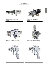
MIST-LESS GUN

English

MIST-LESS SPRAYGUN

Art 199

70

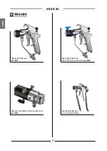
MIST-LESS SPRAYGUN 
MIST-CLEAN version with nozzle 

Art. 199

75  

V

VERSIONS

MIST-LESS AUTOMATIC SPRAYGUN high fisnish 

Art. 11820

MIST-LESS SPRAYGUN
with long filter 

Art. 11946

Summary of Contents for MIST-LESS 09

Page 1: ...ENGLISH PAINTING EQUIPMENT MIST LESS 09 OPERATING AND MAINTENANCE INSTRUCTIONS OPERATING AND MAINTENANCE INSTRUCTIONS ...

Page 2: ......

Page 3: ...g Spraying nozzle p 12 PROBLEMS AND SOLUTIONS p 13 TRIGGER LOCK p 14 Trigger lock engaged p 14 Trigger lock disengaged p 14 ROUTINE MAINTENANCE p 15 Inspecting the valve for obstructions or damge p 15 Valve needle and seal service p 15 EXPLODED DIAGRAM OF MANUAL MIST LESS 07 SPRAYGUN p 16 PNEUMATIC PUMPS FOR MIST LESS SPRAY PAINTING p 18 APPLICATIONS p 19 VERSIONS p 20 WE ADVISETHE USE OFTHIS EQUI...

Page 4: ...ced over the nozzle and the trigger on the spray gun Do not put your fingers in the spray gun nozzle Once work has been completed before carrying out any maintenance complete the decompression procedure explained in this manual Report any danger of electric shock if the warning and presence of live electrical parts has not been indicated Store in a dry place and do not expose to the rain Check tha...

Page 5: ...aks with your hand body or other Do not point gun at anyone or at any part of the body Never spray without tip guard Do pressure relief if you stop spraying or being servicing sprayer and before any maintenance operations Do not use components rated less than sprayer Maximum Working Pressure Never allow children to use this unit Brace yourself gun may recoil when triggered If high pressure fluid p...

Page 6: ... OPENING CONTROL AIR INLET INLET PORT SIZE WEIGHT 140 bar 2030 psi ø 8 ø 6 Gj 1 4 M 550 g 2002A 600 g 2002PLC MIST LESS GUN MANUAL Version MAX OPERATING PRESSURE AIR INLET INLET PORT SIZE WEIGHT 140 bar 2030 psi Gj 1 4 M M16x1 5 M STANDARD Gj 1 4 M 1 4 NPS M 590g MIST LESS GUN PARTS OF THE SPRAYGUN IN CONTACT WITH THE MATERIAL Stainless steel AISI 420B PTFE Aluminium Inox AISI 303 Tungsten carbide...

Page 7: ...SCRIPTION OFTHE EQUIPMENT POS 1 2 3 4 POS Nozzle Closing ring nut Trigger lock Gun body Description Description 5 6 7 8 Spraygun air adjustment screw Spraygun air inlet fitting Trigger Material inlet fitting 1 3 7 2 1 3 5 5 4 6 8 ...

Page 8: ...cement of one or more parts composing the machine the use of accessories tools expendablematerialsotherthan those recommended by the manufacturer can be a danger of accident The manufacturer will be relieved from tort and criminal liability KEEPYOURWORK PLACE CLEAN ANDTIDY DISORDER WHERE YOU ARE WORKING CREATES A POTENTIAL RISK OF ACCIDENTS ALWAYS KEEP PROPER BALANCE AVOIDING UNUSUAL STANCE BEFORE...

Page 9: ...ible hose and accessories with which it can come into contact Never use paints or sol vents containing halogen hydrocarbons as the methylene chloride Iftheseproductscomeintocontactwithaluminium parts can provoke dangerous chemical reactions with risk of corrosion and explosion IFTHE PRODUCTTO BE USED ISTOXIC AVOID INHALATION AND CONTACT BY USING PRO TECTION GLOVES GOGGLES AND PROPER FACE SHIELDS T...

Page 10: ...r amputation Also fluid injected or splashed into the eyes or on the skin can cause serious damage FLUID INJECTION HAZARD Always follow the Pressure Relief Procedure at right before cleaning or removing the fluid nozzle or servicing any system equipment F PRESSURE RELIEF PROCEDURE Toreducetheriskofseriousinjury includingfluidinjection splashing in the eyes or on skin always follow this procedure w...

Page 11: ...y to recouple high pressure hose or mend it with tape or any other device A repaired hose cannot contain the high pressure fluid Handle and route hoses carefully Tighten all fluid connections securely before each use High pressure fluid can dislodge a loose coupling or allow high pressure fluid to be emitted from the coupling Never use a damaged hose If any of these conditions exist replace the ho...

Page 12: ...tic sparking ground the pump and all other equipment used or located in the dispensing area Check your local electrical code for detailed grounding instructions for your area and type of equipment and be sure to ground all of the following equipment Pump groundthepumpbyconnectingagroundingwirefrom the pump s grounding lug to a true earth ground Air compressor or hydraulic power supply ground accor...

Page 13: ...essary Thepressureadjustmentwilldependonhoselength theviscosity of the fluid and the nozzle size To dispense fluid with the gun start the supply pump disengage the trigger lock and squeeze the trigger in all the way Fluid flow beings with the slightest pressure and stops when trigger is released O OPERATION Toreducetheriskofseriousinjury includingfluid injectionorsplashingintheeyesoronskin always ...

Page 14: ...d you can start working STARTINGTHE SPRAYING OPERATIONS Before starting the pump it is important that a small amount of atomizing air is sent to the spraygun ADJUSTING SPRAYING NOZZLE The spraying nozzle can be adjusted according to need by setting the pump operating pressure and the atomization pressure until reaching the required operating conditions For proper spraying of the product the air an...

Page 15: ...or worn Leaks from the gaskets Nozzle dirty or clogged Gasket loosened or worn Nozzle worn Insufficient fluid feed Air in the paint feed line Nozzle worn Nozzle partially clogged Nozzle worn or partially clogged Nozzle clogged Filter clogged or worn Replace with a smaller one If possible dilute the product Replace with a filter with larger mesh Replace the O ring Replace the gaskets Change to a mo...

Page 16: ...OCK DISENGAGED To disengage the trigger lock Q1 rotate the trigger lock backward TRIGGER LOCK TRIGGER LOCK ENGAGED To engage the trigger lock release the trigger and rotate the trigger lock Q1 forward Q1 Q1 Trigger locked Trigger released ...

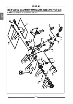
Page 17: ...isassemble the gun as instructed then clean and inspect the parts Replace any worn or damaged parts and reassemble the gun as instructed VALVE NEEDLE AND SEAL SERVICE PLEASE NOTE for details see the exploded diagram on page 16 If fluid flows beyond the seal the gaskets 8 or the rod 34 might be damaged or worn To replace them follow the procedure described below Be sure to read the WARNING see page...

Page 18: ...agram of MANUAL MIST LESS 07 SPRAYGUN WARNING Always indicate code and quantity for each part required 2 1 3 4 11 12 10 5 11 15 6 29 27 26 28 30 31 42 25 45 19 21 20 43 18 8 8 13 14 11 16 16A 17 41 36 35 34 33 32 22 9 37 38 39 40 7 23 24 46 ...

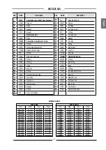
Page 19: ...Elastic ring Bush O Ring Air adjustment screw Bushing Material hose Spraygun cap Elastic ring Union rapid Swivel connection 271 14039 1 11931 12211 4077 12209 12208 12207 12206 11925 11926 11612 M 11906 M 33013 3 12103 11987 1 33013 7 11967 1 11917 11970 1 12202 12471 11781 11155 Art 1501 M 1502 M 1503 M 1504 M 1506 M 1507 M 1508 M 1510 M 1511 M 1512 M 1514 M 1515 M 1516 M 1517 M NOZZLETABLES MIST...

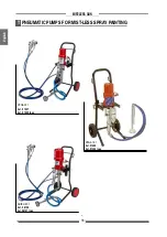
Page 20: ...18 MIST LESS GUN English VEGA 23 1 Art 91507 Art 91509 Inox VEGA 15 1 Art 91400 Art 91405 Inox GHIBLI 30 1 Art 96135 Art 96137 Inox T PNEUMATIC PUMPS FOR MIST LESS SPRAY PAINTING ...

Page 21: ...19 MIST LESS GUN English OMEGA 23 1 Art 7340 Art 7345 Inox U APPLICATIONS ...

Page 22: ...SS GUN English MIST LESS SPRAYGUN Art 19970 MIST LESS SPRAYGUN MIST CLEAN version with nozzle Art 19975 V VERSIONs MIST LESS AUTOMATIC SPRAYGUN high fisnish Art 11820 MIST LESS SPRAYGUN with long filter Art 11946 ...

Page 23: ...GUN English AIRLESS AUTOMATIC SPRAYGUN LA95 Art 11700 LOW PRESSION SPRAYGUN MA98L Art 11300 RA88 AUTOMATIC LOW PRESSURE PUMP RAC2 AUTOMATIC LOW PRESSURE PUMP V71 MANUAL LOW PRESSURE PUMP V77 MANUAL LOW PRESSURE PUMP ...

Page 24: ...22 MIST LESS GUN English MANUAL SPRAYGUN PLA MANUAL SPRAYGUN Airless Art 11702 MANUAL SPRAYGUN AT250 Airless Art 11200 MANUAL SPRAYGUN AT300 Airless Art 11000 MANUAL SPRAYGUN L91X Airless Art 11130 ...

Page 25: ...Due to a constant product improvement programme the factory reserves the right to modify technical details mentioned in this manual without prior notice ...

Page 26: ...RTE LECCO ITALY Via Stoppani 21 Tel 39 0341 62 11 52 Fax 39 0341 62 12 43 E mail larius larius com Internet http www larius com Manufacturer DIRECT LINE Tel 39 0341 621256 Fax 39 0341 621234 CUSTOMERS TECHNICAL SERVICE ...

Reviews: