5
B
ASSEMBLY INSTRUCTIONS
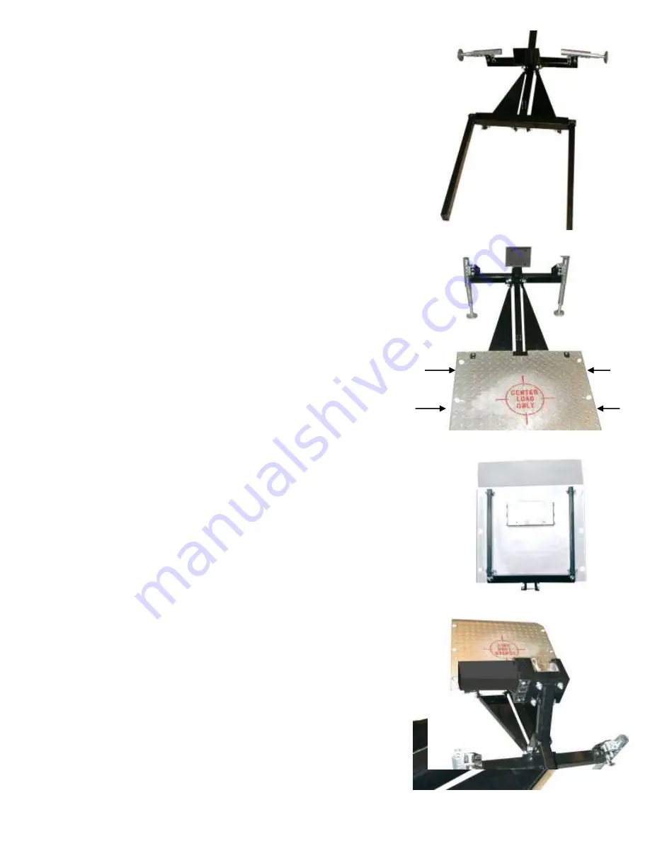
6 Position the Platform Arms onto the Pivot Tube
D
Do not use any fasteners at this time, simply slide the Platform Arms (E)
onto the ends of the Pivot Tube (D)
B B
The assembly should now look like this…………………………….
7 Install the Deck Plate onto the Platform Arms
Begin by moving the outrigger assemblies into the down position.
Remove the quick release pins that secure the outrigger assemblies, rotate the outriggers
down, and then replace the quick release pin to lock them in place. Remove the pins that hold
the inside tubes in the outrigger assemblies, and move them to the lowest position.
Replace the quick release pins and securing clips. This will help to support the assembly
in a convenient position for this step.
Now lower the Deck Plate onto the Platform Arms, aligning the holes. Using a
screwdriver or punch to help align the holes, insert an M10 x 55 bolt (#1) through each of
the four holes. These holes are located where shown by the arrows.
The assembly should now look like this…………………………….
8 Secure the Deck Plate to the Platform Arms
Using an assistant, raise the Deck Plate into the upright position. While the helper
holds the Deck Plate up, install an M10 washer (#3) and an M10 nylon lock-nut (#2) onto each
of the M10 bolts (#1). Install the two quick release pins and clips in the deck plate. Notice
that there is a place to mount your license plate on the bottom of the Deck Plate if needed.
The assembly should now look like this………………………………….
9 Install the Motorized Cable Module to the Hitch Adapter Plate
The Motorized Cable Module is in a separate carton inside the main carton. Packed
With it are four socket head cap screws, washers and nylon lock-nuts. Also enclosed
Is a hex key (Allen wrench) for the socket head cap screws. Start one of the cap screws
through from the inside of the cable module. Use the hex key to hold it in place. Using
your assistant to help hold the cable module, position it from the front placing the cap
screw through the corresponding hole in the Hitch Adapter Plate. Now while the
assistant holds the cable module and the hex key, go around to the back of the assembly
and install one of the washers and nylon lock-nuts. Do not tighten this nut all the way yet.
Repeat installing the other three cap screws from the front and installing the washersand
nylon lock-nuts. Now you can tighten all four nuts securely.
The assembly should now look like this……………………………………


